Industrial brush is widely used for many applications and available in different shapes. It is hard to see them in daily life as normally they work in factories and plants for industrial purposes.
Types Of Industrial Brush
There are 4 main types for industrial brush.
This is a most commonly used one for industrial brush. It is in round shape, and consist of shaft, body and filament. Body are tufted with filament, then installed on shaft. The application is more than we can imagine. Below are some industries:
- Rolling Mills
- Fruit And Vegetable Processing
- Woodworking
- Cow Scratching
- Plate Processor
- Conveyor Cleaning
- Glass Washing
- Solar Panel Cleaning
- Pharmaceutical Industry

This brush is in strip form, and its main application is for industrial sealing for doors. The backing can be metal channel, flexible rubber or rigid plastic. Below are some of its applications:
- Door And Window Sealing
- Production Line Sealing
- Concrete Block Production
- Data Center
- Woodworking
- Conveyor Cleaning
- Metal Sheet Or Window Fabrication

3, Disc Brush
This kind industrial brush is made by round plastic plate combined with filament on one side. Center of plastic plate is with a mounting hole. Tufted disc brush and moulded disc brush are all available. Below are some main applications:
- Road Sweeping
- Floor Scrubbing
- CNC Machine
- Aluminum Wheel Polishing
- Drill Bit

This brush is 2 or 4 wires twisted with filament. The top can be cut, one tuft, plastic cap, bend. The end can be handle, threaded, loop, cut. Below are some main applications:
- Boiler Cleaning
- Tube Cleaning
- Pipe Cleaning
- Engine Polishing And Deburring
- Valve Guide Cleaning
- Medical Device Cleaning

Above are 4 main types for industrial brushes. There are also many nonstandard brushes for industries purposes.
Bristle Materials For Industrial Brush
How to choose bristle materials is very important when producing industrial. It depends on materials of working surface. From light duty to heavy duty, the bristle materials are:
- Nylon
- Polypropylene
- PBT
- PE
- Horse Hair
- Pig Hair
- Goat Hair
- Tampico
- Abrasive Filament
- Steel Wire
- Stainless Steel Wire
- Brass Wire
- Brass Coated Wire
- Phosphorous Bronze
Strip brushes are versatile industrial components widely used across multiple industries, including door and window sealing, conveyor belt cleaning, concrete block production, dust prevention, and machinery protection. The performance and lifespan of a strip brush largely depend on the strip brush material chosen. In this article, we will explore the most common options for both the backing and the bristles, helping you select the right material for your application.

Structure of a Strip Brush
A standard strip brush is composed of two main parts:
- Metal Backing
typically formed into a U-shape, providing the structural base. - Bristles
securely clamped into the backing with a retaining rod, designed to perform sealing, cleaning, or polishing tasks.
By combining different backing and bristle materials, manufacturers can create customized brushes that meet diverse industrial requirements.
Metal Backing Materials
Galvanized Steel Strip Brush
A Galvanized steel strip brush is the most commonly used type because it meets the needs of general applications while remaining cost-effective. Galvanized steel is durable, corrosion-resistant under normal conditions, and ideal for sealing doors, windows, and conveyor systems. For example, galvanized steel backing is widely applied in door bottom sweep brushes, offering a reliable and affordable sealing solution.
Stainless Steel Strip Brush
When higher performance is required, a stainless steel strip brush is the preferred choice. Stainless steel provides superior rust resistance, making it suitable for industries where hygiene and durability are critical. In the food and pharmaceutical sectors, stainless steel ensures cleanliness, while in chemical environments exposed to acids, alkalis, or moisture, stainless steel backing prevents premature corrosion and extends product lifespan.

Bristle Materials
The bristles of a strip brush can be made from a variety of materials, each designed for specific applications.
Nylon Strip Brush
A Nylon strip brush is one of the most popular options, known for its excellent flexibility, durability, and wear resistance. Nylon performs well under repeated friction and is suitable for sealing, dust removal, and light cleaning tasks. It also has better resilience compared to polypropylene, making it ideal for long-term use.

Steel Wire Strip Brush
For heavy-duty applications, a steel wire strip brush is the best option. Steel wire bristles provide aggressive cleaning, rust removal, and surface preparation. These brushes are often used in industrial cleaning equipment, welding applications, and environments where high-strength abrasion is required.
Horsehair Strip Brush
A horsehair strip brush is softer compared to synthetic and metal bristles, offering excellent anti-static properties. This makes horsehair ideal for delicate applications such as electronics, laboratory equipment, and fine dust cleaning, where static discharge could cause damage.
Other Bristle Materials
- Polypropylene
Affordable and lightweight, commonly used for general sealing and dust prevention. - Tampico
A natural fiber with good heat resistance, often used in woodworking for polishing and finishing applications.
Choosing the Right Strip Brush Material
Selecting the proper strip brush material depends on your specific application needs:
- For cost-effective sealing: choose galvanized steel strip brushes with polypropylene bristles.
- For environments requiring corrosion resistance: choose stainless steel strip brushes with nylon or horsehair bristles.
- For heavy-duty cleaning: choose steel wire strip brushes.
- For delicate or anti-static tasks: choose horsehair strip brushes.

In advanced electronic drive systems, precise frequency control is the foundation of reliable operation. Oscillator circuits generate the timing signals that govern switching actions in power electronics, synchronize digital control units, and maintain steady communication between components. Without accurate oscillator performance, even well-designed motor drive systems can suffer from instability, increased losses, or reduced efficiency.
As motor technologies evolve, the requirements placed on oscillators have become increasingly demanding. In electric vehicle (EV) drive motors, switching frequencies must remain consistent under rapidly changing load conditions. Robotics and servo applications depend on precise oscillation to achieve exact positioning. Unmanned aerial vehicles (UAVs) require stable timing sources to maintain responsive motor control during flight. Similarly, industrial frequency inverters rely on oscillator circuits to regulate high-power motors with minimal harmonic distortion.

The role of oscillators in motor drive systems
Motor control requires accurate timing signals to regulate voltage, current, and switching frequency. Even minor frequency drift can lead to inefficiencies, higher heat generation, or unstable operation. For example, in electric vehicle drive motors, the precise coordination between the inverter and motor ensures smooth torque delivery and higher energy efficiency. Oscillators serve as the backbone of this synchronization by providing stable clock references.
In robotics and servo motors, frequency stability directly affects positioning accuracy. Industrial robots executing repetitive tasks rely on synchronized control loops. A fluctuation in oscillator frequency may cause delays or errors, resulting in reduced precision. Similarly, servo systems that require microsecond-level accuracy depend on oscillators with low jitter and excellent temperature stability.
Crystal oscillators as the preferred solution
While various oscillator technologies exist, crystal oscillators are widely adopted in motor drive applications because of their superior stability. Quartz crystals exhibit a highly consistent resonance frequency, which is far less affected by temperature, vibration, or aging compared to LC oscillators or RC oscillators. This reliability makes them an essential component in demanding fields such as:
Unmanned aerial vehicle (UAV) motor control: where flight stability and navigation systems demand consistent timing references to avoid control instability.
Industrial frequency inverters: which regulate large motors in factories. These systems require oscillators that can operate accurately across wide temperature ranges while minimizing electromagnetic interference.
High-precision robotics: where every small deviation in frequency can influence servo accuracy and process efficiency.
Challenges to frequency stability
Despite their inherent advantages, oscillators can still face challenges in maintaining frequency stability under real-world conditions. Key factors include:
Temperature variations – Wide environmental ranges, especially in automotive and outdoor applications, can shift oscillator frequency.
Mechanical stress and vibration – In UAVs and EVs, constant vibration can degrade timing accuracy.
Aging effects – Over long operational periods, crystal parameters gradually change, which can affect resonance frequency.
Power supply noise – Fluctuations in supply voltage may induce jitter or frequency instability.
Addressing these challenges requires careful design considerations and advanced oscillator technologies.
Methods to improve oscillator frequency stability
Several techniques are employed to enhance stability and ensure reliable motor drive performance:
Temperature-compensated crystal oscillators (TCXO): By integrating temperature sensors and compensation circuits, TCXOs minimize frequency drift across broad thermal ranges, making them suitable for EV inverters and outdoor robotics.
Vibration-resistant packaging: Specialized oscillator housings reduce sensitivity to mechanical shocks, enhancing reliability in UAVs and industrial machinery.
Low-jitter differential oscillators: Essential for servo control systems, these oscillators provide clean timing signals that support precise motion control.
Redundant oscillator designs: In safety-critical systems such as autonomous vehicles, dual or redundant oscillators ensure continuous operation even in case of failure.
Application case studies
- In new energy vehicle drive motors, crystal oscillators ensure consistent inverter switching, allowing maximum energy conversion efficiency and extending battery life.
- In robotics, they enable stable synchronization of multiple servo axes, resulting in smoother motion and higher productivity.
- In UAV motor control, frequency stability supports rapid flight adjustments, enabling drones to maintain stable navigation even in turbulent environments.
- In industrial variable-frequency drives, oscillators stabilize switching frequencies, reducing harmonic distortion and improving overall system efficiency.
Improving frequency stability in oscillator circuits is not simply a matter of enhancing component specifications; it is about enabling reliable, precise, and energy-efficient operation across diverse high-performance applications. From electric vehicles to industrial robotics and UAVs, crystal oscillators form the timing foundation that makes advanced motor control possible. As industries continue to demand higher precision and efficiency, further innovation in oscillator design—especially in temperature compensation, vibration resistance, and low-jitter performance—will remain essential to advancing the capabilities of modern electronic systems.
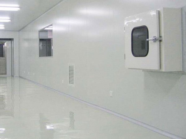
In modern industrial production, cleanliness is a critical factor in many industries, such as food processing, electronics manufacturing, and biomedicine. To ensure a clean and sterile production environment, air showers have emerged as an efficient and essential device. They serve not only as a physical barrier but also as an invisible guardian, ensuring product quality and safety.
Necessity and Importance
Air showers are the essential gateway between non-clean areas and clean areas. Their importance lies in their ability to effectively reduce dust, particles, and bacteria introduced by people and goods entering and exiting the cleanroom, thereby maintaining high cleanliness levels within the cleanroom. This equipment uses high-pressure clean airflow to fully drench the human body, rapidly removing attached contaminants and providing a solid defense for the cleanroom.
Multiple Functions and Intelligent Applications
Air showers are more than just simple showering equipment; they incorporate a variety of intelligent features. For example, smart air showers provide voice prompts to guide users through the showering process, improving efficiency while ensuring a thorough cleansing experience. Furthermore, the front and rear doors of the air shower room feature electronic interlocking, preventing the ingress of unpurified air and further enhancing its function as an "airlock."
In terms of automated control, modern air showers generally utilize PLC intelligent control. LED displays provide real-time information on the air shower's operating status, the interlocking status of the two doors, and the progress of the shower cycle, providing operators with clear and intuitive feedback. Furthermore, the introduction of infrared sensing automatic showering technology makes the air shower process more intelligent and user-friendly, reducing manual operation while improving showering accuracy and efficiency.

Wide Application and Scenario Adaptability
Due to its wide applicability and flexibility, it has been widely used across various industries. In the food industry, it helps reduce cross-contamination within production workshops and ensure product hygiene quality. In electronics manufacturing, it effectively prevents dust from affecting precision equipment, improving product yield and reliability. In the https://www.klcintl.com/biopharmaceutical industry, it is a critical device for maintaining a sterile environment and preventing microbial contamination. Furthermore, various types and specifications have been developed to meet the needs of different industries and scenarios, such as single-person single-blow air showers, multi-person double-blow air showers, and corner air showers, to meet the needs of different occasions. Furthermore, a variety of materials are available, including stainless steel, steel plates, and color-coated steel plates, to meet the corrosion resistance and aesthetic requirements of different environments.
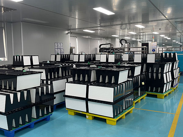
In air conditioning systems for high-purity environments such as cleanrooms, fan-filter units (FFU) are one of the core devices for achieving air cleanliness control. Through their efficient air filtration and stable airflow distribution, FFU ensure the purity and uniform distribution of indoor air. They work collaboratively with dry coil units (DC) and other components to maintain cleanroom environmental conditions.

High-Efficiency Air Filtration and Airflow Distribution
FFU, with their built-in HEPA filters, remove airborne particles, including dust, bacteria, and viruses, ensuring that the air delivered to the cleanroom meets high cleanliness standards.
FFU also utilize their built-in fans to create stable vertical laminar or turbulent airflow, preventing localized contamination. This stable airflow is crucial for maintaining cleanroom cleanliness, especially in the https://www.klcintl.com/semiconductor manufacturing and https://www.klcintl.com/biopharmaceutical industries, where cleanliness requirements are extremely high.
Cooperation and Application Scenarios
In dry coil systems, FFU work collaboratively with dry coil units (DC) and other components, such as the main air handling units (MAU). The MAU is responsible for introducing and processing outdoor fresh air, removing particulate matter through primary and secondary filtration, and conditioning the fresh air to the specified temperature and humidity.
The fresh air treated by the MAU is mixed with a portion of the return air, filtered by the FFU, and then delivered to the cleanroom. The indoor air is cooled or heated by the dry coil before being recirculated to the return air duct and mixed with the fresh air, forming a closed-loop air circulation system.
The FFU operates continuously to maintain air circulation frequency and ensure indoor air cleanliness. The dry coil adjusts the chilled water flow or temperature based on temperature sensors, handling only the sensible heat load and avoiding interference with temperature and humidity control. This clear division of labor improves overall system performance and reliability.
Among the many FFU products available, the KLC FFU is an excellent choice on the market for its superior performance and flexible design. Utilizing KLC's proprietary high-efficiency filters, the KLC FFU achieves highly efficient air filtration, ensuring high indoor air cleanliness.
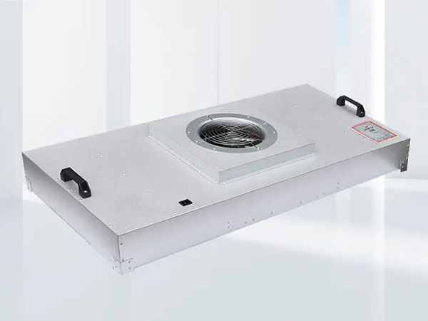
Its compact design makes it easy to install and maintain, while also offering low noise levels and high energy efficiency, meeting the requirements of various cleanliness levels. The KLC FFU also offers flexible installation options and intelligent control options, enabling single-unit manual control or group monitoring of multiple units, adapting to cleanroom applications ranging from small to large-scale.
The KLC FFU has demonstrated outstanding performance in practical applications, particularly in fields such as https://www.klcintl.com/semiconductor manufacturing, https://www.klcintl.com/biopharmaceuticals, and precision electronic assembly, providing users with efficient and reliable air purification solutions. Its efficient filtration performance and stable airflow distribution effectively prevent condensation from contaminating wafers, ensuring a sterile environment in pharmaceutical production while also safeguarding the accuracy and stability of the equipment.
The KLC FFU's low noise operation and energy-efficient design also excel in cleanrooms with stringent environmental requirements, making it an ideal air filtration option.
As the core air filtration device in dry coil systems, the FFU provides a reliable solution for high-purity environments such as cleanrooms through its efficient filtration capacity and stable airflow distribution. Its synergistic operation with the dry coil and other components further optimizes system performance and reliability.
In fields such as https://www.klcintl.com/semiconductor manufacturing, https://www.klcintl.com/biopharmaceuticals, and precision electronic assembly, the FFU has become a critical piece of equipment for maintaining high-purity environments, ensuring efficient and stable production processes.
In chip manufacturing plants, even a speck of dust as small as 0.1 microns can render an entire wafer scrapped; in sterile operating rooms, bacterial intrusion directly threatens surgical safety. In these environments, where cleanliness is crucial, HEPA filters serve as the "last line of defense" protecting the air.
KLC As an industry service provider with years of experience in air purification, we'll break down the technical secrets of HEPA filters and how they create a clean barrier for various industries.
Basic Principles of HEPA Filters
1. Physical Interception: Micron-Scale "Air Screening"
Using ultrafine glass fibers or composite filter media, nanometer-scale pores (over 1,000 times smaller than the diameter of a human hair) are formed between the fibers, acting like a precision sieve that directly intercepts particles larger than these pores. The Shangjing HEPA filter utilizes a gradient pore design, achieving a 99.9% interception rate for particles larger than 5μm.
2. Inertial Collision: Traps Particles
When airflow suddenly changes direction while passing through filter media fibers, larger particles (0.5-10μm) are deflected by inertia and directly collide with and adhere to the fibers. This principle is particularly critical in the high-speed airflow systems of https://www.klcintl.com/semiconductor plants, quickly capturing fine debris generated by metal processing.
3. Diffusion Effect: A "Brownian Motion Trap" for Nanoparticles
Viruses and nanoaerosols smaller than 0.1μm experience random motion due to molecular thermal motion, increasing the probability of contact with the filter media. Our electrostatically charged filter media technology improves diffusion efficiency by 30%, achieving a 99.99% filtration efficiency for the novel coronavirus (approximately 0.1μm).
4. Electrostatic Adsorption: Giving the Filter Media a "Magnetic Coat"
The electret treatment imparts static electricity to the filter media. The charged fibers can attract particles of opposite charge, even polarizing neutral particles. In PM2.5 control scenarios, this technology can increase the filtration efficiency of submicron particles to over 99.97%.
Its Function and Role in Cleanrooms
Stability Does Not Require Compromise
1. Providing Ultimate Air Purification
High-efficiency filters effectively remove tiny particles, bacteria, viruses, and other harmful substances from the air, ensuring that the air cleanliness within the cleanroom meets predetermined standards. In chip manufacturing workshops in the electronics and https://www.klcintl.com/semiconductor industry, air cleanliness requirements are extremely high. Even the smallest dust particles can cause chip defects and affect product quality.
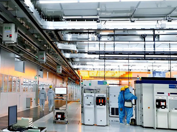
High-efficiency filters effectively remove airborne particles 0.3μm or smaller, typically achieving a filtration efficiency of over 99.97% for particles as small as 0.3μm. Some ultra-high-efficiency filters even achieve filtration efficiencies as high as 99.9995%, providing a nearly dust-free clean air environment for chip manufacturing and meeting the stringent air quality requirements of the production process.
2. Maintaining a Stable Clean Environment
High-efficiency filters operate continuously and stably, providing uninterrupted, highly efficient filtration of air entering the cleanroom, thereby reducing the accumulation and spread of particulate matter within the cleanroom. They not only prevent the intrusion of external contaminants but also rapidly remove pollutants generated by human activity and production processes, helping to maintain a stable cleanliness within the cleanroom and achieve a dynamic cleanroom balance.
In medical operating rooms, the movement of personnel and the operation of equipment generate a certain amount of dust and microorganisms. High-efficiency filters continuously filter the air, effectively removing these pollutants and maintaining a high level of cleanliness within the operating room, thereby reducing the risk of surgical infection.
In precision instrument manufacturing workshops, the production process may generate trace amounts of pollutants such as metal debris and dust. High-efficiency filters quickly remove these pollutants, ensuring the air in the workshop remains clean, providing a stable environment for precision instrument manufacturing and safeguarding the accuracy and performance of products.
3. Protecting Downstream Equipment and Products
In cleanrooms, high-efficiency filters are typically installed at the end of the air handling system, providing the final purification step for air entering the cleanroom. This not only ensures the cleanliness of the cleanroom environment but also protects downstream equipment and products from contamination and damage from harmful airborne particulate matter.
In https://www.klcintl.com/semiconductor manufacturing equipment, key components such as optical lenses and silicon wafers are extremely sensitive to dust. Even the smallest amount of dust particles can cause equipment failure or degrade product quality. High-efficiency filters effectively intercept airborne particulate matter, preventing it from entering the equipment, thus protecting its normal operation and product quality. In aseptic filling plants in the food and beverage industry, high-efficiency filters remove airborne microorganisms and dust, preventing contamination of food and beverage products, extending their shelf life, and safeguarding consumer health.
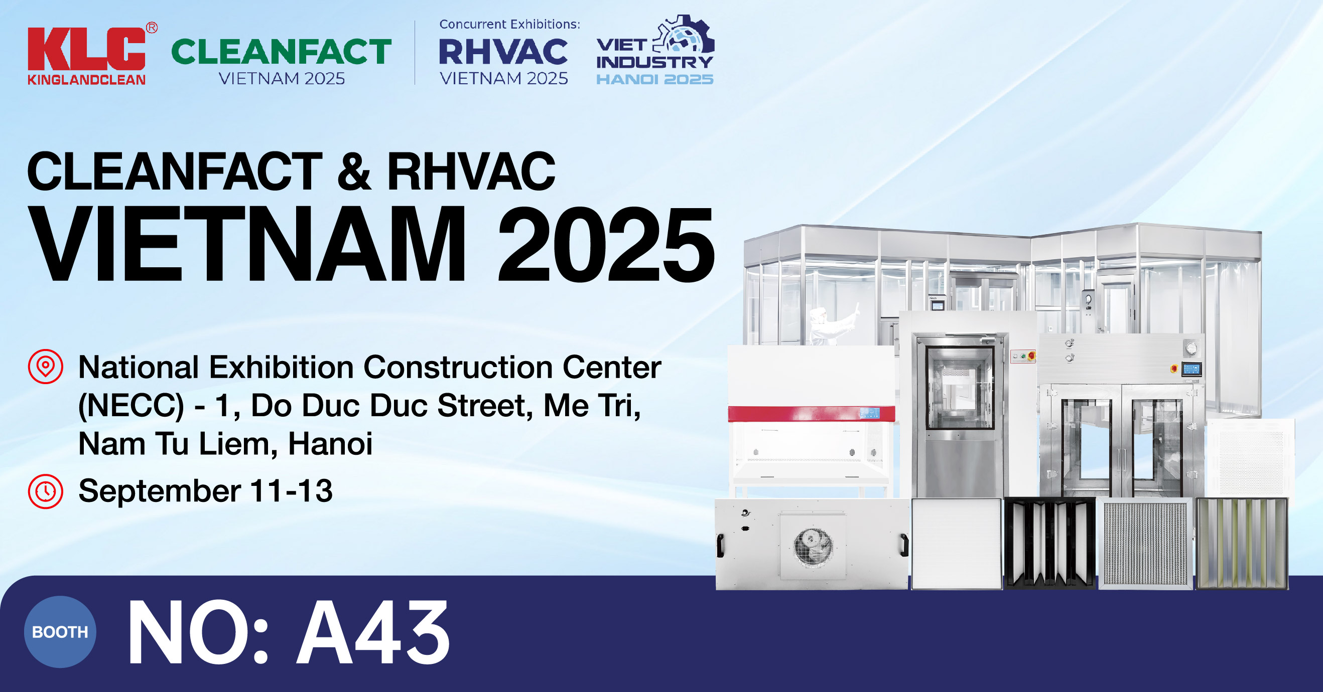
We are thrilled to announce that KLC will be at CLEANFACT & RHVAC VIETNAM 2025! This is the premier event for the cleaning, sanitation, and HVAC-R industries in Vietnam, and we can't wait to be a part of it.
BOOTH No: A43
11–13 September 2025
Join us to:
Explore our latest innovations in air filtration.
Engage in insightful discussions on the future of clean air technology.
Connect with our experts and discover solutions for your needs.
Let's collaborate to shape a healthier, cleaner future. We look forward to seeing you there!
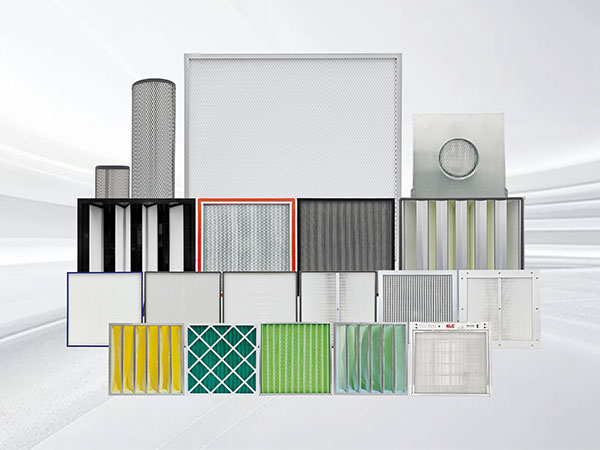
Air filters are a type of air filter characterized by high filtration precision, high resistance, and high cost. They are essential consumables for industrial cleanrooms. Recent advances in air filtration technology, including the research and development of filter media, filtration mechanisms, and the development and application of filtration equipment, have significantly boosted the development of air filters!
Industrial Cleanrooms
Industrial cleanrooms require continuous and effective removal of even smaller particles. HEPA filters were once used for end-of-line filtration, while ULPA filters are now the highest-precision ultrafiltration filters. They generally utilize fine glass fiber filter media, but membranes and electrostatically enhanced media have also made inroads into this field, seeing some experimental application and achieving significant progress. The most stringent requirements for exhaust gases emitted by production plants are toxic gases. Filters used in industrial cleanrooms will continue to evolve in line with modern technology, aiming for higher precision, lower filtration resistance, and more effective performance.

Pharmaceutical Factory Sterile Workshops
The production environment in pharmaceutical factory sterile workshops must strictly control microbial and particulate contamination. Industrial air filters employ a three-stage filtration system: a primary filter (G4) intercepts large dust and hair particles, a medium-efficiency filter (F8) further filters particles larger than 1 micron, and a high-efficiency filter (H13) effectively intercepts particles 0.3 microns. In addition, some workshops are equipped with chemical filters at the end, filled with activated carbon or chemical adsorbents, to remove residual harmful gases and odors from the air and prevent pharmaceutical contamination. To ensure sterility, the filter frames are often made of antimicrobial materials. After installation, they must undergo integrity testing (such as PAO testing) to ensure the sealing and effectiveness of the entire filtration system.
Food Processing Workshops
Food processing workshops must prevent dust and microbial contamination while also controlling odors from the production process (such as cooking fumes in bakery rooms and odors in fermentation rooms). Industrial air filters employ food-grade filter media, such as antimicrobial-treated polyester fiber filters, to prevent secondary contamination of food. In addition, activated carbon filters are widely used in odor treatment, quickly removing odor molecules through the physical adsorption of high iodine value activated carbon.
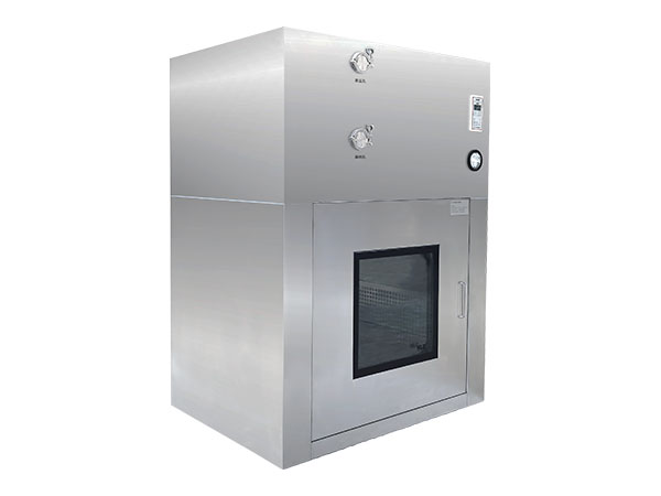
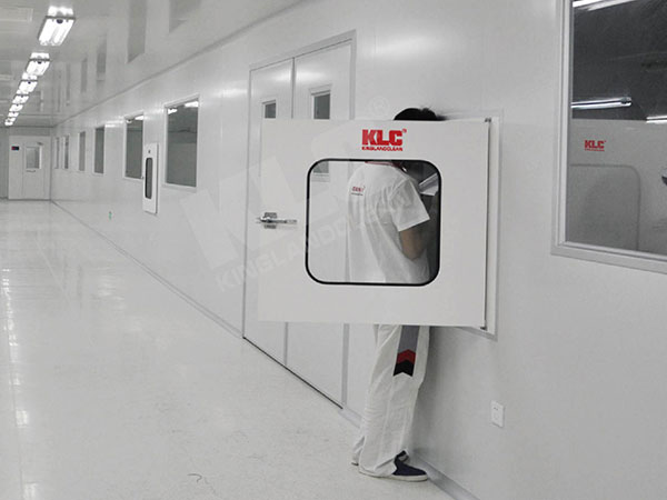
In hospital clean areas, you might often see gleaming stainless steel Pass Box. While seemingly ordinary, they're actually "invisible guardians" of infection control.
1. Rust-Free = Safer
Ordinary Pass Box can rust and peel over time, becoming a breeding ground for bacteria. Stainless steel, on the other hand, is corrosion-resistant and easy to disinfect. For example, while hydrogen peroxide fumigation is commonly used in operating rooms, ordinary materials might corrode, but stainless steel Pass Box can withstand it.
2. Sealing Comparable to a Safe
Pass Box used in hospitals must be "leak-proof." For example, when chemotherapy drugs are delivered in a pharmacy, a loose seal could allow toxic particles to escape. High-quality stainless steel Pass Box feature an airtight design, preventing even air from escaping.
3. Unexpected Function: Labor Savings
Hospitals have calculated that traditional Pass Box require frequent manual disinfection, while stainless steel Pass Box with self-cleaning features (such as UV light and high-efficiency filtration) save over 200 man-hours annually.
Conclusion:
Do you think hospitals are just obsessed with appearance? In fact, every design is a race against microorganisms.
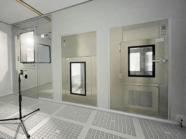
In the cleanroom, the heart of a food factory, every breath of air and every surface plays a crucial role in the safety and quality of the final product. How can materials, tools, and semi-finished products flow safely, efficiently, and contamination-free between clean and non-clean areas? This requires a quietly unsung yet crucial "invisible guardian"—the professional clean passbox!
01 Isolating Contamination, Protecting Purity
Double-Door Interlock: Ensures both doors cannot be opened simultaneously, effectively blocking external contaminants such as dust and microorganisms from entering the cleanroom with the airflow.
High-Efficiency Filtration: A built-in High-Efficiency Particulate Air (HEPA) filter continuously purifies the air during the transfer process, maintaining a positive pressure environment and preventing cross-contamination.
Smooth and Easy-Clean: Made of food-grade materials such as 304/316L stainless steel, the surface is smooth, with no dead spots or risk of debris, making it easy to thoroughly clean and disinfect.
02 Improve Efficiency and Optimize Processes
Convenient Operation: The ergonomic design and smooth opening and closing significantly shorten material transfer time, reduce the frequency of personnel entering and exiting the cleanroom, and minimize contamination risks. Standardized Management: Clear transfer processes (such as UV disinfection and wiping procedures) ensure that each transfer complies with standard operating procedures (SOPs).
03 Compliance Assurance for Audit Preparedness
Regulatory Compliance: Strict adherence to cleanroom logistics channel requirements of food industry standards such as GMP, HACCP, and ISO 22000 is essential for preparing for various certification audits.
Traceability: Comprehensive transfer records (optional electronic record functionality) provide a basis for quality traceability.
- Automotive Engine Rubber Parts8
- Automotive Lamps Rubber Parts5
- Automotive Suspension Rubber Parts2
- Automotive Wiring Harness Rubber Parts3
- Extrusion Sealing Strip1
- Industrial Electrical Rubber Parts3
- Industrial Scanners2
- Industrial electrical control3
- Industrial slings4
- Machine Tool Blades1
- Membrane Products1
- Motor1
- Racecource Rubber Products3
- Rubber Forklift Attachments1
- Rubber and plastic Parts1
- Seal2
- Tubular Motor2
- blade1
- brush1
- chip1
- industrial hose1
- lens1
- mold1
- plc3
- pump2
- racking2