Carbon Molecular Sieve serves as the core adsorbent inside PSA nitrogen generators, directly determining nitrogen output stability, energy consumption and long-term operational safety of on-site nitrogen generation systems.
Many purchasers and system engineers rush into purchasing decisions relying merely on quotations or basic laboratory data without comprehensive evaluation. Improper CMS selection may trigger reduced nitrogen purity, frequent equipment shutdowns, rising maintenance costs and even potential operational safety hazards.
This article outlines six prevalent pitfalls in CMS procurement and delivers practical evaluation criteria for buyers of PSA nitrogen generation equipment.
1. Prioritizing Upfront Price While Ignoring Long-term Operating Costs
It is a widespread pitfall for purchasers to prioritize low pricing when comparing carbon molecular sieves. Nevertheless, comprehensive operating costs ought to be the primary evaluation benchmark. CMS with inferior separation efficiency features a poor air-to-nitrogen ratio, consuming more compressed air throughout its service life and increasing power load on air compressors. Accumulated extra electricity bills over several years will far exceed the upfront savings from choosing low-cost adsorbents.
In addition, low-grade CMS suffers faster performance degradation and shorter service life. Frequent shutdowns for replacement disrupt continuous production and incur extra labor expenses and production downtime losses. Instead of simply comparing unit prices, enterprises should calculate total costs based on nitrogen output, air-to-nitrogen ratio and expected service lifespan.
2. Neglecting Mechanical Strength and Anti-Pulverization Performance
Some purchasers only focus on nitrogen separation indicators while overlooking the physical properties of CMS pellets. Subjected to continuous air flow impact, alternating pressure and tank vibration, carbon molecular sieves with low crush strength will gradually pulverize. Circulating carbon powder blocks filters and control valves, elevates system pressure drop and impairs nitrogen supply quality.
Most Shanli CMS models achieve a crush strength above 38 N, while high-end customized versions can exceed 60 N. Superior mechanical strength effectively prevents pulverization, which is particularly critical for marine nitrogen generation systems and underground nitrogen injection equipment under persistent vibration.
3. Deploying General-Purpose CMS Directly in Harsh Working Conditions Without Customized Adaptation
Many users assume one universal carbon molecular sieve fits all application scenarios. In fact, CMS formulations are optimized for specific operating environments. Standard industrial-grade CMS lacks sufficient tolerance to high humidity, salt spray and frequent start-stop cycles. When directly deployed on vessels, underground mines or other severe working sites, its micropores will be quickly clogged by moisture and contaminants, leading to rapid deterioration of nitrogen separation efficiency.
Working conditions including vibration intensity, ambient humidity, target nitrogen purity and operation continuity shall be clarified in advance. We are capable of developing customized CMS tailored to specific project requirements.
4. Overlooking Batch Consistency of Carbon Molecular Sieves
Unstable batch quality remains a prominent issue for certain manufacturers. One batch of products may deliver satisfactory performance, whereas the subsequent batch sees obvious nitrogen output decline. Fluctuating CMS performance forces operators to repeatedly adjust parameters of PSA equipment and undermines stable nitrogen supply.
Shanli implements standardized full-process production monitoring starting from raw material screening. Strict sampling tests are conducted for every batch to guarantee consistent separation performance and eliminate risks arising from quality discrepancies across batches.
5. Lack of Awareness Regarding Raw Material Differences for CMS Production
Raw material quality fundamentally defines the microstructure of carbon molecular sieves. Some manufacturers adopt biomass, waste or recycled feedstocks. Such materials feature high ash content, tend to form irregular pore structures and generate excessive mesopores. CMS manufactured from these feedstocks delivers unstable adsorption-desorption characteristics, with efficiency dropping sharply after short-term operation.
Shanli collaborates with material suppliers to develop resin-based foam precursors exclusively for CMS production. Low ash content and outstanding consistency support stable micropore formation. Under identical filling volume, it can produce more nitrogen than conventional carbon molecular sieves, with highly overlapping adsorption and desorption curves and stable cyclic performance.
6. Placing Bulk Orders Without Preceding Laboratory Simulation Tests
Numerous buyers confirm large orders solely based on static data provided by suppliers. The technical parameters offered by manufacturers are usually obtained under ideal laboratory conditions. Any deviation in on-site temperature, pressure and air pretreatment status will alter actual gas production results. If CMS fails to meet purity requirements after tank filling, modification and replacement will cause substantial financial losses.
Laboratory testing can simulate real operating conditions, optimize PSA parameters and verify matching performance, enabling customers to fully assess practical CMS capacity prior to bulk procurement.
7.Select Reliable Carbon Molecular Sieves to Mitigate Procurement Risks
To avoid the pitfalls mentioned above, partners should select suppliers with mature core technologies, rigorous quality control and comprehensive technical support. Qualified CMS suppliers shall deliver consistent product performance and provide professional guidance for application commissioning.
Further Reading: Five Core Advantages of Shanli Carbon Molecular Sieve: Reliable Adsorbent for On-site PSA Nitrogen Generation
8.Conclusion
Carbon molecular sieve procurement constitutes a long-term investment rather than a one-off transaction. Comprehensive evaluation covering service life, air-to-nitrogen ratio, mechanical strength, batch stability and raw material foundation carries far greater weight than merely chasing low prices. Beyond premium CMS products, Shanli also provides laboratory simulation testing, on-site equipment commissioning and sample supply services to help customers achieve optimal nitrogen generation efficiency.
Feel free to contact us if you require performance data, sample testing or customized carbon molecular sieve solutions for your PSA nitrogen generation project.
Carbon molecular sieve acts as the core adsorbent for PSA nitrogen generators, directly determining nitrogen output, purity stability, operating expenditure and overall service life of gas production systems.
Shanli carbon molecular sieve is widely adopted across semiconductor, petrochemical, mining and marine industries for on-site nitrogen generation. Supported by proprietary material technology, strict manufacturing control and verified performance data, Shanli CMS stands out amid competitive alternatives.
This article elaborates on five core advantages of Shanli CMS, together with our comprehensive supporting technical services for partners and end users.
1. Extended Service Life with Strong Anti-pulverization Performance
Under standard air pretreatment conditions, Shanli carbon molecular sieve features a typical service life ranging from 5 to 10 years. Many customers report even longer operating cycles when equipment and air source conditions are well maintained.
Most Shanli CMS grades achieve a single-pellet crush strength above 38 N, while high-performance customized models can reach over 60 N. Superior mechanical strength effectively reduces particle friction and pulverization caused by continuous airflow impact, vibration and pressure fluctuation, making our products suitable for challenging scenarios including underground mines and ocean-going vessels.
Furthermore, customized CMS formulations are available to match various complicated working environments.
2. Lower Long-term Operating Costs Backed by Optimized Air-to-Nitrogen Ratio
The air-to-nitrogen ratio is a decisive indicator that governs power consumption of PSA nitrogen systems. Shanli CMS delivers outstanding separation efficiency, cutting compressed air consumption and reducing electricity expenses for air compressors. Longer service intervals also minimize downtime and maintenance costs caused by frequent adsorbent replacement.
Take SLCMS-USP/L as a reference, tested under 0.7 MPa and 20 ℃ :
- For 99.99% purity nitrogen: 110 Nm³ nitrogen per ton of CMS per hour, air-to-nitrogen ratio at 3.5
- For 99.9% purity nitrogen: 150 Nm³ nitrogen per ton of CMS per hour, air-to-nitrogen ratio at 2.9
3. Proprietary Micropore Modulation Technology
Micropore structure dominates the oxygen-nitrogen diffusion separation process. Shanli has developed independent micropore modulation technology to precisely adjust pore size and pore distribution of carbon molecular sieve.
With optimized microstructure, Shanli CMS achieves uniform micropores without redundant mesopores. Its adsorption and desorption curves show high coincidence, ensuring stable cyclic separation performance. We are capable of adjusting micropore characteristics according to customers' targeted nitrogen purity requirements, developing tailored CMS grades for different nitrogen production specifications.
4. Standardized Full-process Production Monitoring Based on Premium Raw Materials
Consistent product quality relies on strict control from raw material selection to finished product inspection.
Shanli cooperates with suppliers to develop exclusive resin-based foam precursors specially manufactured for CMS production. Unlike biomass materials, waste materials or recycled feedstock, this premium raw material features low ash content, high consistency and great development potential. High-quality precursors guarantee stable micropore formation during production.
Our quality management covers the whole workflow: raw material screening, pellet forming, carbonization, activation, modification and random sampling inspection. Rigorous full-process monitoring effectively avoids inconsistent performance between batches, ensuring stable quality for every shipment of carbon molecular sieve.
5. High Nitrogen Output Capacity
Benefiting from premium raw materials and mature micropore regulation technology, Shanli carbon molecular sieve delivers higher nitrogen output under the same filling volume compared with conventional CMS.
It can maintain stable nitrogen purity even under relatively high load, supporting large-flow PSA nitrogen generators. This advantage helps equipment manufacturers design more compact nitrogen systems or boost gas production capacity without expanding tower size.
6. Complementary Professional Technical Support
Beyond high-performance CMS products, Shanli provides complete technical services to maximize system efficiency for PSA nitrogen equipment manufacturers and factories requiring adsorbent replacement.
6.1 In-house laboratory testing
We can simulate customers' actual operating conditions, adjust technical parameters and explore the optimal matching scheme to bring out the full potential of Shanli CMS.
6.2 On-site equipment tuning service
Professional technical support is available to optimize operating parameters of PSA nitrogen generators and achieve stable target nitrogen output.
6.3 Sample supply
Samples are offered for preliminary performance verification before bulk orders.
7.Conclusion
Selecting suitable carbon molecular sieve is vital for sustainable and economical on-site nitrogen production. With long service life, favorable operating cost, proprietary micropore modulation technology, standardized full-process manufacturing and high nitrogen output, Shanli CMS provides reliable adsorption solutions for diversified PSA nitrogen projects. Coupled with laboratory testing and on-site technical services, we support partners throughout the whole project cycle.
If you want to learn more details or need sample testing, please feel free to contact us.
In the fast-paced world of metal fabrication, precision, speed, and sustainability are non-negotiable. For industries ranging from automotive to aerospace, CNC sheet metal machinery has become the backbone of modern manufacturing. Acu Sheet Metal Machine stands at the forefront of this revolution, offering state-of-the-art equipment designed to streamline workflows, reduce waste, and deliver flawless results.
1. Maximize Productivity with CNC Sheet Metal Machinery
Gone are the days of manual, error-prone metal cutting. Acu’s CNC sheet metal machinery combines computer-controlled precision with robust engineering, enabling manufacturers to produce complex parts at unmatched speeds. These machines excel in high-volume production, ensuring consistent quality while minimizing material waste. Features like automatic tool changers and real-time diagnostics reduce downtime, making them indispensable for factories aiming to meet tight deadlines.
Pro Tip: Pair Acu’s CNC punching machines with CAD/CAM software to automate design-to-production workflows and slash lead times by up to 40%.
2. Laser-Sharp Accuracy with Precision Laser Cutting Machines
When it comes to intricate designs and ultra-thin materials, precision laser cutting machines are the gold standard. Acu’s fiber laser systems deliver micron-level accuracy, effortlessly slicing through stainless steel, aluminum, and alloys with minimal heat distortion. Ideal for industries like electronics and medical device manufacturing, these machines ensure clean edges and burr-free finishes, eliminating the need for secondary processing.
Why It Matters: By integrating IoT-enabled monitoring, Acu’s laser cutting solutions empower operators to track energy consumption and optimize efficiency—key for eco-conscious businesses.
3. Streamline Complex Bends with Automated Bending Systems
Bending thick metal sheets with precision is no small feat. Acu’s automated bending systems leverage robotic arms and AI-driven angle correction to achieve flawless bends repeatedly. Whether crafting HVAC components or automotive chassis, these systems reduce human error and labor costs. The programmable backgauges and multi-axis capabilities allow for rapid setup changes, catering to both small batches and mass production.
Case in Point: Acu’s hydraulic press brakes are engineered with overload protection, ensuring durability even under heavy-duty workloads.
Why Choose Acu Sheet Metal Machine?
Acu Sheet Metal Machine isn’t just a supplier—it’s a partner in innovation. Their CNC sheet metal machinery, laser cutting systems, and automated bending solutions are built to adapt to Industry 4.0 demands, prioritizing smart manufacturing and sustainability. With energy-efficient designs and global compliance certifications, Acu empowers businesses to stay competitive in a rapidly evolving market.
From CNC-driven precision to laser-cutting agility and automated bending versatility, Acu’s machinery lineup addresses the core challenges of modern metal fabrication. Investing in advanced equipment isn’t just about keeping up—it’s about leading the charge toward smarter, greener, and more profitable production.
The global manufacturing industry is entering a new phase of transformation. As supply chains continue to adapt to shifting market demands and manufacturers pursue greater production flexibility, automation, energy efficiency, and digital manufacturing have become the core topics shaping the metal forming sector in 2026. More companies are investing in intelligent production lines that reduce labor costs while enabling faster product customization.
Against this backdrop, choosing the right roll forming machine is no longer just about producing metal profiles—it's about building a smarter, more competitive factory.
Smart Manufacturing Is Driving the Next Generation of Roll Forming
In recent months, discussions around AI-assisted production, predictive maintenance, and digital factory upgrades have become increasingly common across the manufacturing industry. Equipment suppliers are responding by developing production systems that integrate automation, precision control, and real-time monitoring.
Modern roll forming machine technology now offers manufacturers several competitive advantages:
- Faster production cycles with consistent quality
- Reduced material waste through precision forming
- Lower labor dependency via automated operation
- Flexible profile switching for customized orders
- Easier integration with Industry 4.0 manufacturing systems
For businesses serving construction, furniture, solar energy, home decoration, and industrial equipment markets, these capabilities translate directly into higher productivity and stronger profitability.
Meeting Growing Demand for Decorative Metal Products
The global interior decoration and commercial renovation sectors continue to expand, creating increasing demand for high-quality metal decorative profiles. From residential projects to luxury hotels and retail spaces, manufacturers require equipment capable of producing aesthetically consistent products while maintaining high output.
One excellent example is the photo frame roll forming machine, specifically designed for producing decorative metal frame profiles with exceptional dimensional accuracy and surface quality. Its advantages include:
- High-speed continuous production
- Stable forming precision
- Excellent compatibility with various steel and aluminum materials
- Reduced setup time for different profile designs
- Lower production costs through automated operation
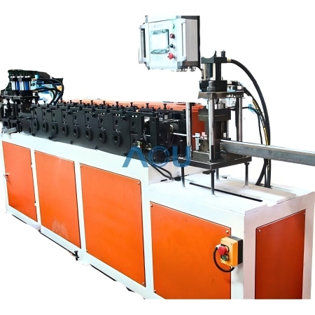
As consumer expectations for premium interior products continue to rise, manufacturers equipped with automated roll forming solutions gain a significant competitive advantage.
Automated Production Is Transforming Sandwich Panel Manufacturing
The rapid expansion of logistics centers, cold storage facilities, clean rooms, modular buildings, and renewable energy projects has fueled strong demand for insulated sandwich panels worldwide. To meet increasing production requirements, manufacturers are moving away from semi-automatic processes toward fully integrated production lines such as automatic sandwich panel production equipment.
These advanced systems deliver:
- Continuous automated production
- Precise thickness and density control
- Improved bonding consistency
- Higher production efficiency
- Lower operating costs over long production runs
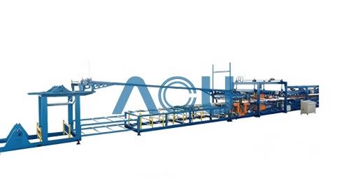
With governments around the world promoting energy-efficient buildings and sustainable construction, automated sandwich panel production is expected to remain one of the fastest-growing segments in the metal forming industry.
Why Equipment Reliability Matters More Than Ever
Market uncertainty has encouraged manufacturers to focus not only on expanding production capacity but also on maximizing equipment uptime. Reliable machinery provides long-term value through:
- Stable performance during continuous operation
- Reduced maintenance frequency
- Higher production consistency
- Faster return on investment
- Better adaptability to changing market requirements
Rather than simply purchasing equipment, today's manufacturers are seeking long-term production partners capable of supporting future business growth.
ACU Sheet Metal Machine: Supporting Global Manufacturers
At www.acusheetmetalmachine.com, we understand that every production line represents a long-term investment. Our engineering team focuses on delivering customized roll forming solutions that combine precision engineering, intelligent automation, and dependable performance.
Whether customers are expanding production capacity, upgrading existing factories, or entering new markets, we provide equipment designed to improve manufacturing efficiency while supporting future digital transformation.
From standalone machines to fully integrated production lines, our solutions help manufacturers stay competitive in an industry where flexibility, automation, and product quality have never been more important.
Looking Ahead
The manufacturing landscape in 2026 is evolving faster than ever. Companies that embrace automation, intelligent production, and flexible manufacturing systems will be better positioned to respond to changing customer demands and global market opportunities. Investing in advanced roll forming technology is no longer simply an equipment decision—it is a strategic investment in long-term competitiveness.
If your business is planning its next production upgrade, visit www.acusheetmetalmachine.com to explore innovative roll forming solutions engineered for the future of smart manufacturing.
In slitting production, many users retrieve circular blades from long-term warehouse storage and find yellowish-brown rust spots on the cutting edge. When faced with rust spots, the most common concern is: do these rust spots affect cutting performance? Can the blade still be used? Mingbai Mechanical Tool Technology Co., Ltd., based on materials science and field experience, provides scientific judgment criteria and handling recommendations.
1. The Nature and Hazards of Rust Spots
Rust spots are the product of electrochemical reactions between the blade's metal surface and oxygen and moisture in the air. For precision mechanical blades made of high-carbon steel, high-speed steel, and similar materials, once rusting begins, it penetrates from the surface inward. The harm of rust spots depends on three factors: location, depth, and morphology.
2. Three Types of Rust Spots on the Cutting Edge
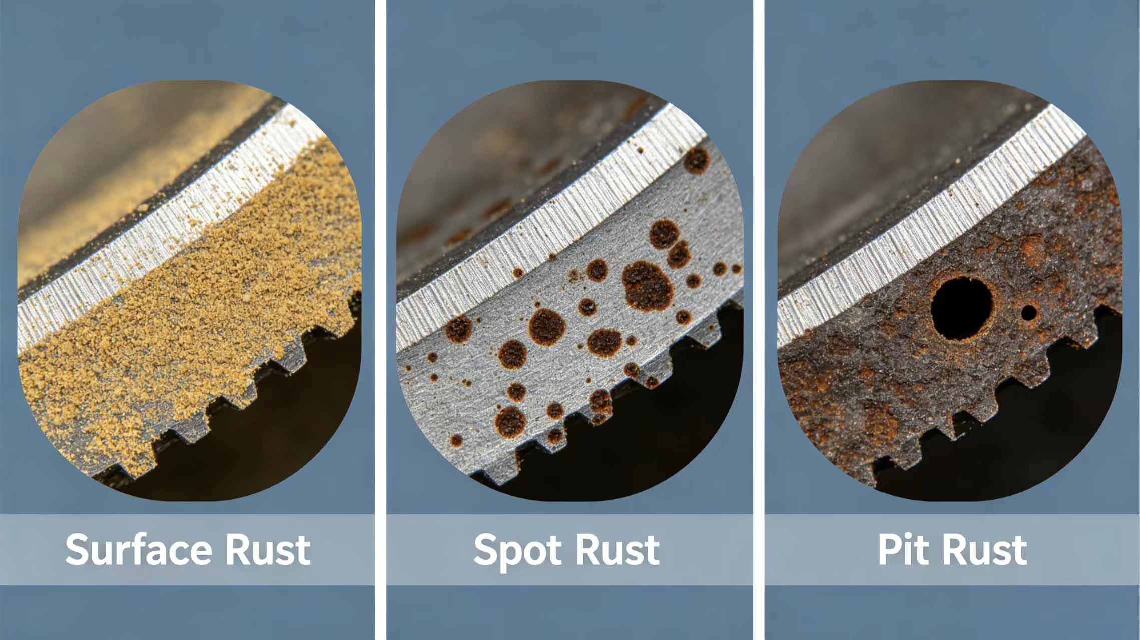
Surface flash rust (mild)
Characteristics: Yellowish-brown powdery rust, present only on the surface, depth < 0.01mm, removable with a cloth.
Impact: After removal, no visible pits remain on the edge — does not affect performance.
Pitting rust (moderate)
Characteristics: Dark brown or black spots, depth 0.01-0.03mm, leaving tiny pits the size of a pinprick after removal.
Impact: May affect cutting quality, depending on specific working conditions.
Pitted/crater rust (severe)
Characteristics: Dark brown or black depressions, depth > 0.03mm, leaving obvious pits or grooves after removal.
Impact: Significantly affects performance, causing burrs or chipping during cutting — replacement is recommended.
3. Four-Step Method to Determine Whether Rust Spots Affect Performance
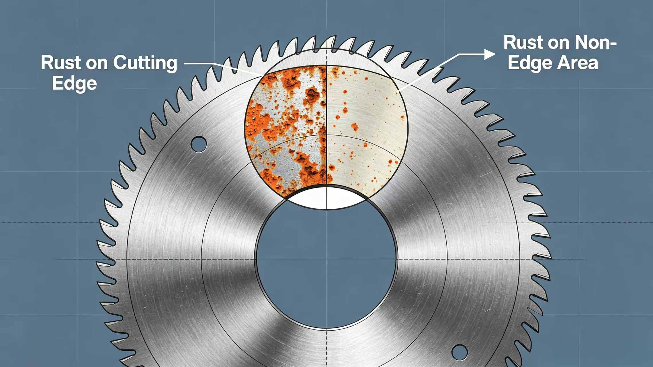
Step 1: Check the rust spot location
Rust spots on the cutting edge → directly affect cutting quality and require careful handling. Rust spots on the blade body (non-edge areas) → do not affect performance; clean and use. Inspection method for rust spots on stored circular blades starts with location.
Step 2: Assess rust spot depth
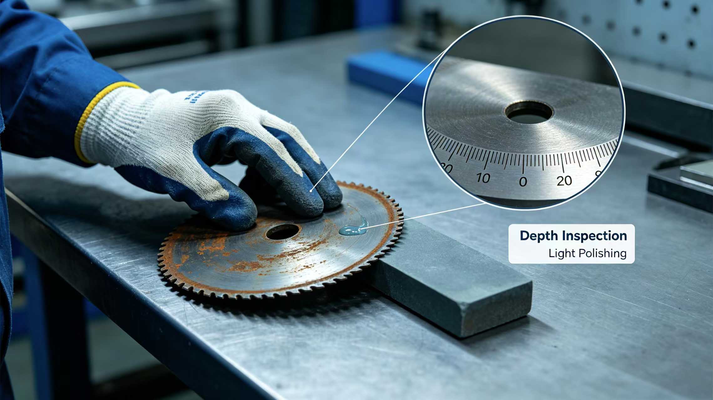
Gently sand the rusted area with fine sandpaper or an oilstone. If the surface is flat without pits after sanding → flash rust, can continue to be used. If obvious pits remain → rust has penetrated the substrate; assess whether edge integrity is compromised.
Step 3: Check edge integrity
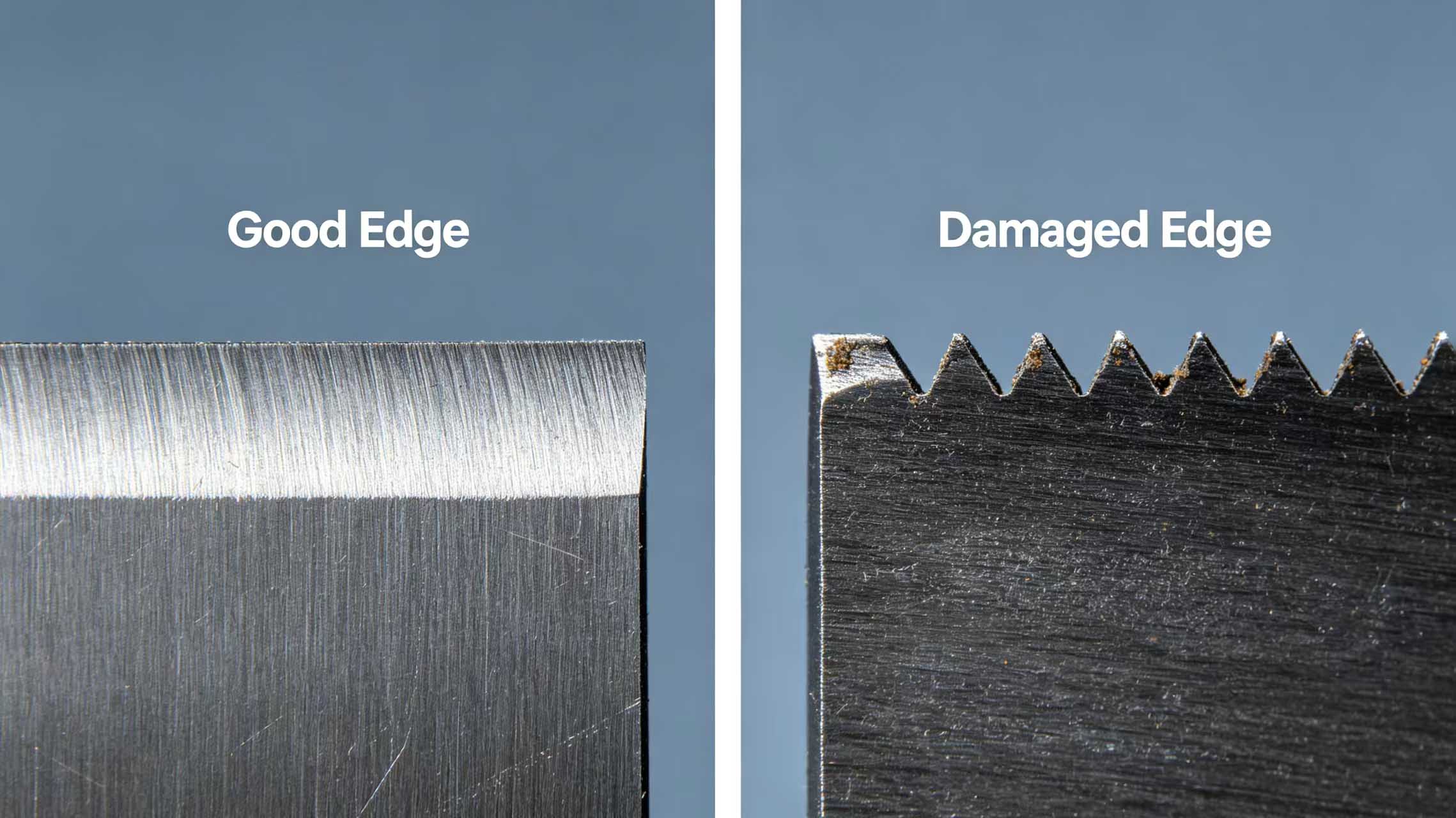
Use a magnifying glass to inspect the edge. If the edge remains straight and intact → rust has not damaged the edge geometry. If the edge appears jagged or has notches → rust has damaged the edge, and circular blades for precision slitting will directly affect cutting accuracy.
Step 4: Verify through trial cutting
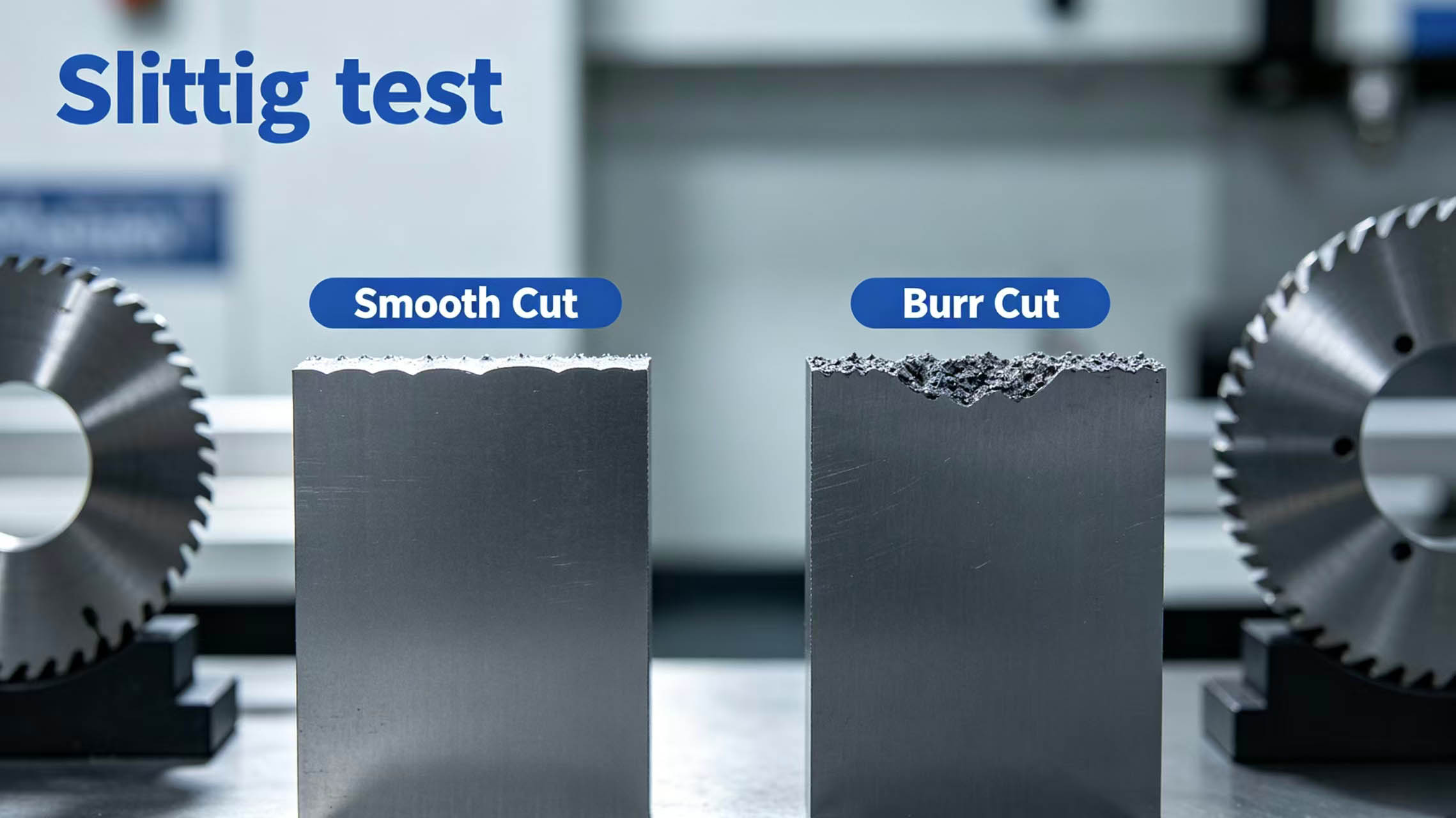
After cleaning the rust, perform a trial cut. Smooth cut edge without burrs → performance restored. Obvious burrs or uneven edges → rust has affected performance; recommend replacement or return to factory for regrinding.
4. Rust Tolerance of Different Blade Materials
High-speed steel circular blades: Most sensitive to rust. Pitting deeper than 0.02mm is recommended for replacement.
Carbide blades: The substrate does not rust, but the cobalt binder phase may corrode; edge strength must be checked.
Stainless steel blades: Good corrosion resistance. Rust spots usually stay on the surface with shallow depth. Ultra-thin circular blades for food packaging film slitting are more sensitive to defects and require special attention.
Coated blades: Rusting tends to occur where the coating is damaged; confirm whether rust has penetrated the coating.
5. Rust Removal Methods
Flash rust removal
Gently sand with a fine oilstone (1000 grit or higher) with oil, or lightly brush with a brass wire brush, then wipe with rust preventive oil for protection.
Moderate rust removal
Sand with fine sandpaper (800-1200 grit) until the surface is bright, taking care not to alter the edge geometry. Then inspect edge integrity with a magnifying glass.
Deep rust treatment
Directly scrap, or send back to Mingbai Technology for evaluation to see if it can be restored through regrinding. If the edge is intact after regrinding, it can continue to be used.
6. How to Prevent Rust Spots in Storage?
· Control storage environment humidity between 40%-60%.
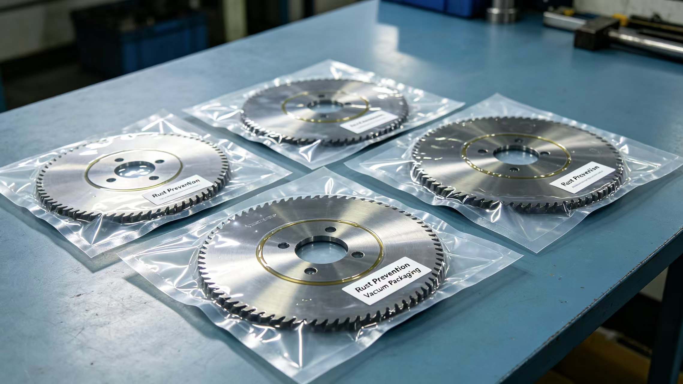
· Long-term stored custom slitter blades should be coated with rust preventive oil and vacuum-packed.
· Regularly inspect inventory, spot-check every 3 months.
· Store blades of different materials separately to avoid galvanic corrosion.
7. Mingbai Technology's Rust Inspection Services
Mingbai Mechanical Tool Technology Co., Ltd. offers rust evaluation for stored circular blades services:
· Free visual inspection to determine rust type and depth.
· Microscope inspection of edge integrity.
· Provide repair or replacement recommendations.
· Professional rust removal and regrinding services for repairable blades.
Conclusion
Rust spots on the cutting edge of circular blades after long-term storage do not necessarily mean the blade is scrap. Surface flash rust can be cleaned and does not affect performance. Pitting rust requires assessment of location and depth. Pitted/crater rust or edge damage should be scrapped or sent back for repair. The key steps are: "check location, measure depth, inspect edge, verify through trial cutting." Mingbai Technology is ready to provide professional rust inspection and repair services for you.
Website: www.mingbaiblade.com
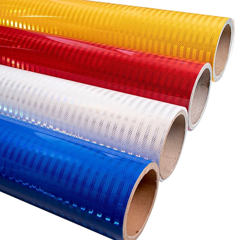
You need the right materials for clear visibility and dependable performance. Engineer grade reflective sheeting stands out as a practical solution for general-purpose applications. Most often, you see it used for advertisement signs, road traffic signs, industrial safety signs, vehicle license plates, parking and directional signs, reflective lettering and numbering, safety identification graphics, construction and industrial signage, and municipal and transportation signs. This type enhances safety and ensures signs stay visible in low-light conditions. Explore more about Engineer Grade Reflective Sheeting to find the best fit for your project.
Key Takeaways
-
Engineer grade reflective sheeting is ideal for general-purpose applications, providing moderate visibility for safety signs and traffic signs.
-
Choose the right material type—glass beads for basic reflectivity, microprisms for superior visibility, and non-metallized films for durability.
-
Always check for ASTM D4956 Type 1 compliance to ensure your reflective sheeting meets minimum reflectivity standards.
-
Evaluate environmental factors like UV exposure and weather conditions to select the most suitable reflective sheeting for your project.
-
Regular inspections and maintenance of reflective signs help preserve visibility and extend the service life of the materials.
What Is Engineer Grade Reflective Sheeting
Features and ASTM Standards
You rely on engineer grade reflective sheeting for dependable performance in a wide range of safety signs and traffic signs. This custom reflective sheeting uses advanced materials to deliver the right balance of visibility and durability. The most common material types include glass beads, microprisms, and non-metallized films. Each material impacts reflectivity and application suitability in unique ways:
|
Material Type |
Description |
Reflectivity Impact |
|---|---|---|
|
Glass Beads |
Embedded in adhesive layers, reflecting light but less bright than microprisms. |
Provides basic reflectivity, suitable for non-critical signage. |
|
Microprisms |
Engineered for intense reflections, offering superior visibility. |
Enhances visibility from longer distances, ideal for safety applications. |
|
Non-metallized |
More durable and weather-resistant materials used in modern tapes. |
Ensures longer-lasting reflectivity for outdoor use. |
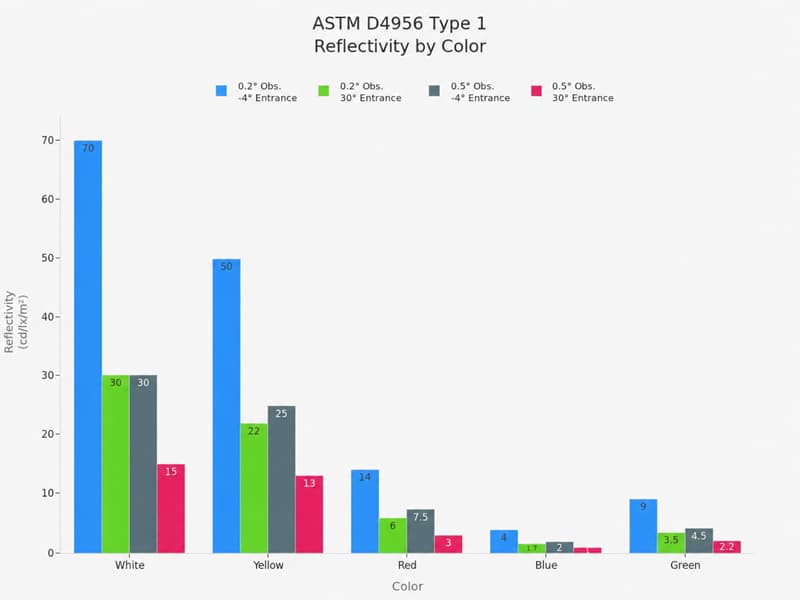
You should always check for ASTM D4956 Type 1 compliance when selecting custom reflective sheeting for safety signs and traffic signs. This standard defines the minimum reflectivity levels for different colors and observation angles. The chart below shows how reflectivity varies by color and angle:
Common Applications
You will find engineer grade reflective sheeting used in a variety of safety signs and traffic signs. This custom reflective sheeting is ideal for general-purpose applications where moderate reflectivity is sufficient. Typical uses include:
-
Parking lot traffic signs
-
Construction zone safety signs
-
Temporary traffic signs
-
Private property safety signs
-
Commercial safety signs
-
Directional traffic signs
-
Industrial safety signs
-
School zone traffic signs
-
Warehouse safety signs
-
Facility safety signs
You benefit from the cost-effectiveness of engineer grade reflective sheeting for non-critical applications. This custom reflective sheeting offers a typical service life of up to 10 years, making it a reliable choice for long-term safety signs and traffic signs. Most manufacturers and regulatory agencies recommend a 10-year replacement cycle for these types of retroreflective sheeting. You get moderate reflectivity and durability without the higher cost of premium grades.
For most non-critical safety signs and traffic signs, engineer grade reflective sheeting provides the right balance of performance and value. You should consider higher grades, such as EGP Reflective Sheeting or PMMA Micro Prismatic Reflective Sheeting, for applications that demand maximum visibility or longer service life.
Key Factors for Choosing Reflective Sheeting
Visibility and Best Sign Reflectivity
You want your reflective sheeting project to deliver increased visibility and safety, especially in low light situations. Engineer grade reflective sheeting provides visibility at night up to approximately 500 feet, making it suitable for non-critical signs. The table below highlights key features:
|
Feature |
Details |
|---|---|
|
Visibility |
Approximately 500 feet |
|
Description |
Uses glass beads or prismatic technology; suitable for non-critical signs |
|
Common Colors |
White, yellow, red, blue, green, brown |
|
Durability |
5–7 years outdoor warranty |
For best sign reflectivity, consider the retroreflectivity values. Engineer grade prismatic reflective sheeting offers strong retroreflectivity, but if your reflective sheeting project requires even greater visibility at night, you may want to explore EGP Reflective Sheeting for higher performance.
Durability and Outdoor Performance
Durability plays a major role in the long-term performance of your reflective sheeting project. Outdoor durability ratings vary by material:
|
Material |
Outdoor Durability |
Printable |
Cuttable |
|---|---|---|---|
|
PMMA |
5-7 years |
Yes |
Yes |
|
PVC |
1-3 years |
Yes |
Yes |
|
PET |
1-3 years |
No |
Yes |
You should select materials that match your application and expected exposure. Increased visibility and retroreflectivity can fade over time, especially with harsh weather or intense sunlight.
Compliance and Regulations
Before you start your reflective sheeting project, check all relevant regulations. The table below summarizes key requirements:
|
Regulation Type |
Description |
|---|---|
|
MUTCD Guidelines |
Ensure minimum standards for nighttime visibility and consistency |
|
State-Specific Rules |
Local DOTs may require stricter standards |
|
ASTM Standards |
Define performance and quality criteria |
|
Regular Inspections |
Maintain compliance with reflectivity levels |
|
Upgrading Options |
Higher-grade materials may improve safety and reduce maintenance |
You must ensure your reflective sheeting project meets both federal and local standards for visibility at night and retroreflectivity.
Application Environment
Environmental conditions directly affect the performance and lifespan of reflective materials. You should consider:
-
UV rays and sunlight exposure can degrade reflectivity and cause discoloration.
-
Weather elements like heavy rain, snow, and extreme temperatures reduce durability and retroreflectivity.
Choosing the right engineer grade reflective sheeting for your application ensures your signs remain effective and visible, even in challenging environments.
Engineer Grade vs. Other Retroreflective Sheetings
Comparing Reflectivity Levels
You need to understand how different reflective sheetings perform when you select materials for safety signs. Engineer grade reflective sheeting offers reliable retroreflectivity for general-purpose applications. The ASTM D4956 Type I standard defines its performance, making it suitable for commercial and non-critical signs. EGP Reflective Sheeting and PMMA Micro Prismatic Reflective Sheeting deliver superior brightness, especially at night. The table below compares key specifications:
|
Specification |
Engineer Grade Reflective Sheeting |
EGP Reflective Sheeting |
PMMA Micro Prismatic Reflective Sheeting |
|---|---|---|---|
|
Type |
ASTM D4956 Type I |
Type II |
Type II/III |
|
Technology |
Glass bead |
Non-metalized micro-prismatic |
Micro-prismatic |
|
Thickness |
16 mil |
16 mil |
18 mil |
|
Durability |
5-7 years |
7 years |
10+ years |
|
Reflectivity |
Moderate |
Superior |
Maximum |
|
Application |
Commercial, non-critical signs |
Regulatory, warning signs |
Regulatory, high-visibility signs |
You can explore more about Engineer Grade Reflective Sheeting for projects where moderate reflectivity meets your needs.
When to Upgrade to EGP or PMMA Micro Prismatic
You should consider upgrading to EGP Reflective Sheeting or PMMA Micro Prismatic Reflective Sheeting when your application demands higher visibility or longer service life. EGP Reflective Sheeting uses advanced micro-prismatic technology, providing enhanced reflectivity for regulatory signs and warning boards. PMMA Micro Prismatic Reflective Sheeting stands out for high intensity prismatic retroreflective sheeting, making it ideal for critical safety applications and areas with strict compliance requirements.
Tip: Choose engineering grade retroreflective sheeting for parking lot signs and temporary construction markers. Upgrade to EGP Reflective Sheeting or PMMA Micro Prismatic Reflective Sheeting for regulatory signs, traffic drums, channelizers, and Type II barricades.
You can learn more about EGP Reflective Sheeting if your project requires enhanced performance and durability.
Cost and Value Considerations
You want to maximize value for your reflective project. Engineer grade reflective sheeting offers cost-effectiveness for non-critical applications. You benefit from stable outdoor reflectivity, strong tear resistance, and reliable adhesion on aluminum panels. For large-scale projects, you find that engineer grade delivers excellent plotter cutting performance and dimensional stability. EGP Reflective Sheeting and PMMA Micro Prismatic Reflective Sheeting justify their higher cost when you need maximum reflectivity and extended service life.
|
Feature |
Engineer Grade Reflective Sheeting |
EGP Reflective Sheeting |
PMMA Micro Prismatic Reflective Sheeting |
|---|---|---|---|
|
Dimensional Stability |
Better |
Excellent |
Superior |
|
Tear Resistance |
Strong |
Strong |
Superior |
|
Outdoor Reflectivity |
Stable |
Enhanced |
Maximum |
|
Adhesion on Aluminum Panels |
Reliable |
Reliable |
Reliable |
|
Plotter Cutting Performance |
Excellent |
Excellent |
Excellent |
|
Common Applications |
Traffic signs, warning boards |
Regulatory signs |
High-visibility signs |
Regular inspections and periodic cleaning help maintain visibility and performance for all grades. Avoid harsh chemicals and high-pressure washing to protect the reflective surface.
You can discover more about PMMA Micro Prismatic Reflective Sheeting for demanding safety applications that require top-tier performance.
How to Determine the Best Retroreflective Sheeting for Your Application
Choosing the right retroreflective sheeting involves more than just picking a product off the shelf. You need to evaluate your project’s unique requirements, match those needs to the correct specifications, and ensure proper installation and ordering. This process helps you maximize reflectivity, safety, and long-term value for your signs.
Assessing Project Needs
Start by analyzing the specific demands of your application. You should consider several critical factors:
-
Supply luminance and demand luminance
-
Viewing geometries, including the angle and distance from which drivers or pedestrians will see the signs
-
Environmental factors that affect visibility, such as weather, dust, and lighting conditions
Demand luminance depends on the driver’s visual abilities, the design of the sign legend, and the distance between the observer and the sign. For example, a sign placed farther from the road or in a poorly lit area requires higher reflectivity to remain visible. You also need to account for real-world conditions:
-
Windshield transmissivity can reduce ideal luminance by up to 30%.
-
Atmospheric transmissivity changes with dust, fog, or rain.
-
The condition of the windshield, such as dirt or haze, can further decrease luminance.
By evaluating these factors, you can determine the best retroreflective sheeting for your application and ensure your signs deliver optimal performance.
Matching Specifications to Requirements
Once you understand your project needs, you must align them with the correct sheeting specifications. Follow these steps to make an informed choice:
-
For federal or state projects, always refer to the MUTCD manual and relevant state regulations.
-
For local projects, consult your city or local engineering department for specific requirements.
You can use the following guide to match your application methods to the right sheeting class:
-
Use Class I engineer grade for low-speed, low-risk areas such as parking lots or private facilities.
-
Choose Class II high-intensity prismatic for urban centers and main roads where higher visibility is necessary.
-
Select diamond grade for high-speed corridors and critical visibility zones.
Note: Focusing only on initial reflectivity and installation costs can lead to higher long-term expenses. Lower-grade reflective films may fail prematurely, resulting in frequent replacements and reduced safety.
Microprismatic sheeting, such as PMMA Micro Prismatic Reflective Sheeting, represents a significant advancement in retroreflective technology. This material uses an array of tiny prisms to reflect light more efficiently than traditional materials. You benefit from a larger and brighter cone of reflectivity, which enhances visibility for drivers from various angles. This makes it ideal for demanding applications where maximum safety and performance are required.
Installation and Quantity Tips
Proper installation and accurate quantity estimation are essential for the success of your reflective signage project. Consider these practical tips:
-
Measure all sign locations carefully to determine the total area of sheeting required.
-
Order a small surplus to account for mistakes or future replacements.
-
Store reflective sheeting in a cool, dry place to maintain its quality before use.
-
Clean the substrate thoroughly before applying the sheeting to ensure strong adhesion.
-
Use recommended application methods, such as squeegees or rollers, to avoid air bubbles and wrinkles.
-
Follow manufacturer guidelines for temperature and humidity during installation.
Tip: Always inspect installed signs periodically. Regular cleaning and maintenance help preserve reflectivity and extend the service life of your reflective materials.
By following these steps and choosing the right application methods, you ensure your signs remain visible, durable, and compliant with safety standards. For projects that demand the highest level of performance, PMMA Micro Prismatic Reflective Sheeting offers a reliable solution that excels in challenging environments.
You make the best choice for reflective projects by focusing on key decision points. Consider the intended application, compare performance levels, and evaluate environmental factors. Always check regulations and follow a compliance checklist for your reflective safety signs. Matching your needs with the right reflective sheeting ensures durability and visibility. For high-visibility requirements, PMMA Micro Prismatic Reflective Sheeting offers premium performance and proven durability.
FAQ
What is Engineer Grade Reflective Sheeting best used for?
You should use Engineer Grade Reflective Sheeting for general-purpose reflective applications. It works well for parking lot signs, facility markings, and non-critical safety projects where moderate visibility is required.
How does EGP Reflective Sheeting differ from standard options?
EGP Reflective Sheeting uses advanced prismatic technology. You get higher reflective brightness and longer durability compared to standard engineer grade materials. Choose EGP for regulatory signs or when you need enhanced nighttime visibility.
Can I use reflective sheeting outdoors in harsh weather?
Yes, you can use reflective sheeting outdoors. Select the right grade for your climate. EGP and PMMA Micro Prismatic Reflective Sheeting offer excellent performance in extreme conditions, keeping your signs visible and reliable.
What is the service life of PMMA Micro Prismatic Reflective Sheeting?
PMMA Micro Prismatic Reflective Sheeting provides a long service life. You can expect up to 10 years of strong reflective performance, making it ideal for demanding safety applications.
How do I choose the right reflective sheeting for my project?
Start by identifying your project’s visibility and durability needs. Consider local regulations and the environment. For high-visibility or critical safety signs, PMMA Micro Prismatic Reflective Sheeting delivers top performance.
Introduction
Global manufacturing is undergoing a structural transformation. After years of supply chain disruptions, rising logistics costs, and intensifying pressure to shorten time-to-market, industrial OEMs across sectors are rethinking how they source custom metal fabricated parts. The default assumption — that in-house machining or local tier-one suppliers offer the best balance of cost, quality, and control — is no longer holding.
In 2026, the precision machined parts market is projected to exceed USD 420 billion globally, driven by accelerating investment in energy infrastructure, industrial automation, and the electrification of transport. At the center of this growth is a decisive shift: more companies are turning to specialized external fabrication partners for components that were once produced internally, and they are sourcing across borders with greater confidence than ever before.
The Post-Pandemic Supply Chain Restructuring
The disruptions of 2020 through 2023 exposed a fundamental weakness in concentrated supply chains. When a single-source supplier in one geography went offline, entire production lines stalled. In response, procurement teams have been systematically diversifying their supplier bases — adding qualified partners across multiple regions to build redundancy and resilience.
For custom fabricated metal parts, this diversification has been especially pronounced. Unlike standardized components or raw materials, precision machined parts carry the embedded knowledge of the fabricator: fixture design, process sequencing, quality control protocols, and material expertise. Finding a new supplier is not a transactional exercise; it requires technical qualification, sample validation, and often several rounds of iterative engineering communication.
Yet the incentive to do so has never been stronger. Companies that successfully build a multi-region supplier network for fabricated components report average lead time reductions of 25–35% and cost savings of 15–20% when benchmarked against single-region sourcing. The key enabler? Improvements in digital communication, 3D design file sharing, and remote inspection technologies have closed the collaboration gap that once made cross-border custom fabrication impractical.
Technology Convergence in CNC and Multi-Axis Machining
The fabrication shop floor of 2026 looks fundamentally different from its counterpart a decade ago. Five-axis CNC machining centers, once the preserve of aerospace and medical device manufacturers, have become accessible to mid-sized fabrication suppliers serving general industrial markets. Combined with advances in CAD/CAM software and in-process measurement systems, these technologies allow a single setup to machine complex geometries that previously required multiple fixtures and manual transfers.
The result is a step change in achievable precision. Tolerances of ±0.005 mm, once aspirational, are now routinely specified and delivered on production runs — not just prototypes. For buyers, this means that a qualified overseas fabrication partner can meet the same dimensional standards as a domestic precision machine shop, often at a substantially lower total cost.
Equally important is the integration of quality assurance into the machining process itself. Modern CNC cells equipped with tool probing, in-process gauging, and automated offset compensation reduce the reliance on post-process inspection. This shift from "inspect quality in" to "machine quality in" is particularly valuable in cross-border sourcing, where the cost of discovering non-conformance after international shipment is punitive.
Industry-Specific Demand Drivers
Three sectors are disproportionately driving demand for custom fabricated metal parts in 2026:
Energy and Power Generation. The global push toward energy transition is not just about solar panels and wind turbines. It requires massive investment in the physical infrastructure that moves, controls, and converts energy: valve bodies, pump components, hydraulic manifolds, heat exchanger parts, and precision structural elements. From natural gas processing facilities in Central Asia to geothermal plants in Southeast Asia, each project demands custom-fabricated components built to exacting material and dimensional specifications.
Industrial Automation and Robotics. As manufacturers across sectors deploy more automated production lines, the need for custom end-effectors, mounting brackets, sensor housings, and kinematic components grows in lockstep. These parts are typically low-volume, high-mix, and impossible to source from catalogs — making them a natural fit for specialized fabrication partners.
Heavy Equipment and Construction Machinery. The global infrastructure investment cycle, fueled by government stimulus programs in North America, Europe, and across the Belt and Road corridor, is creating sustained demand for custom-fabricated structural and mechanical components. Excavator linkages, crane subassemblies, hydraulic cylinder components, and bespoke mounting systems all require the kind of multi-process fabrication — cutting, machining, welding, surface treatment — that integrated suppliers are best positioned to deliver.
Quality Standards and Certification as Competitive Differentiators
In a market where dozens of suppliers claim "precision" and "quality," certifications provide a credible filter. ISO 9001 remains the baseline, but forward-thinking buyers increasingly look for ISO 3834 (welding quality), ISO 2768 (general tolerances), and material-specific certifications depending on application requirements.
For energy-sector applications, GOST certification and compliance with national standards remain critical for projects in CIS countries and Central Asia. For European markets, EN 10204 3.1 material certificates are often non-negotiable. Suppliers that have invested in these certifications — and can produce the documentation to prove it — gain a decisive advantage in both initial qualification and repeat business.
The documentation package itself has become a competitive differentiator. A fabrication partner that delivers not just parts, but a complete quality dossier including material certificates, dimensional inspection reports, surface finish measurements, and process traceability records, removes a significant administrative burden from the buyer's quality team and reduces the risk of supply chain interruptions at customs or end-user acceptance.
The Rise of Integrated Multi-Process Suppliers
Perhaps the most consequential trend in custom metal fabrication is the consolidation of multiple processes under one roof. Historically, a complex fabricated part might travel through five or six specialist shops: a laser cutter, a machine shop, a welding contractor, a heat treater, and a surface finisher. Each handoff introduces lead time, logistical cost, and quality risk.
In 2026, the most capable fabrication suppliers offer integrated workflows: material procurement, CNC machining, welding, heat treatment, surface finishing, and final inspection — all managed within a single quality system. For the buyer, this means a single point of contact, one set of quality documents, and significantly reduced coordination overhead.
This integration is especially valuable for complex assemblies that combine machined components with welded structures. When the same engineering team oversees both the turned part and the welded sub-frame it mounts to, fit-up issues are caught at the design review stage rather than during assembly at the customer's facility thousands of miles away.
Looking Ahead
The custom metal fabrication landscape in 2026 rewards buyers who think strategically about supplier partnerships. The lowest unit price rarely delivers the lowest total cost of ownership. The suppliers that will thrive — and the partners that buyers will stick with — are those that combine technical capability with responsive communication, robust quality systems, and the willingness to invest in understanding their customers' applications.
For procurement professionals and engineering managers seeking a reliable precision fabrication partner, the question is no longer "can we source custom parts from overseas?" but rather "which overseas partner offers the best combination of capability, quality, and long-term reliability?"
Contact Shengtao Metal for Steel Product Solutions
If you are looking for reliable steel and metal product solutions, feel free to send us your inquiry.
Simply provide your specifications such as material grade, dimensions, quantity or application, and our team will respond quickly with professional support and a competitive quotation.
Email: stsalesman4@stmetal001.com
Introduction
Sourcing custom fabricated metal parts from China has moved far beyond the stereotype of commodity fasteners and simple brackets. Today, a well-qualified Chinese fabrication partner can deliver precision-machined components that meet the same engineering standards as European or North American machine shops — often at 30–50% lower total cost. But achieving that outcome depends entirely on how the sourcing process is managed.
This guide walks through the complete procurement lifecycle, from preparing your first technical package to receiving finished parts at your warehouse. Whether you are an engineering manager sending drawings abroad for the first time, or a seasoned procurement professional looking to tighten your supplier qualification process, the principles below will help you reduce risk, compress lead times, and build a fabrication partnership that scales with your business.
Preparing Your Technical Drawings and Specifications
The single most common source of miscommunication in cross-border fabrication is incomplete or ambiguous technical documentation. A drawing that is "good enough" for a domestic supplier you have worked with for years may leave critical gaps when interpreted by a new partner in a different engineering culture.
At minimum, your drawing package should include:
- Fully dimensioned 2D drawings in PDF format, with all critical dimensions clearly identified
- 3D CAD models in a neutral format such as STEP (.stp) or IGES (.igs) — these eliminate ambiguity in complex geometries and allow the supplier to program CAM toolpaths directly
- Material specification including grade, standard reference (e.g., ASTM A276, EN 10088, JIS G4303), and any required material certificates
- Tolerance table referencing an accepted standard (ISO 2768-m or -f is widely used internationally) or custom tolerances called out on individual dimensions
- Surface finish requirements specified in Ra (μm) or RMS (μin), with any critical surfaces clearly marked
- Quantity and packaging requirements, including any special handling or preservation needs
A good practice is to include a one-page specification summary that distills the key requirements. This is not a substitute for detailed drawings, but it helps the supplier's engineering team quickly assess whether the project falls within their capability envelope before they invest hours in detailed review.
Understanding Tolerance Standards and Material Grades
Tolerance specification is where many cross-border projects encounter friction. Different regions default to different standards: ISO 2768 in Europe and much of Asia, ANSI Y14.5 in North America, and JIS B 0405 in Japan. While these standards are largely harmonized at the technical level, the commercial expectation around which standard applies is not always explicit.
When sending drawings to a Chinese fabrication partner, the safest approach is to:
- Explicitly state which tolerance standard applies, e.g., "General tolerances per ISO 2768-m"
- Call out any dimensions requiring tighter than general tolerances directly on the drawing
- Specify geometric tolerancing (flatness, perpendicularity, concentricity, runout) where functional performance depends on it
- If you have GD&T callouts per ASME Y14.5, confirm that the supplier's engineering team is fluent in interpreting them — most experienced export-oriented fabricators are
Material grades present a similar challenge. A specification that reads "304 stainless steel" without an ASTM, EN, or JIS reference leaves room for interpretation. The supplier's default source may use a national standard equivalent that meets chemical composition requirements but differs subtly in mechanical properties. To avoid this, always specify the full material designation: "AISI 304 (UNS S30400) per ASTM A276" or "X5CrNi18-10 (1.4301) per EN 10088."
For critical applications, request a material certificate (EN 10204 3.1 or 3.2) with every shipment. The incremental cost is modest, and the traceability it provides is invaluable if a material-related issue ever arises downstream.
Surface Finishing, Heat Treatment, and Secondary Processes
Custom fabricated parts rarely ship in their as-machined state. Surface finishing, heat treatment, plating, coating, and other secondary processes are often what distinguish a functional part from one that fails prematurely in service — and they are also where quality variability is most pronounced if not properly specified.
Common secondary processes and what to specify:
- Electroplating (zinc, nickel, chrome): Specify plating thickness in microns, the applicable standard (e.g., ASTM B633 for zinc), and any post-plating hydrogen embrittlement relief requirements for high-strength steels
- Anodizing (aluminum): Specify type (Type II decorative or Type III hard coat), color, and thickness
- Heat treatment: Specify process (quench and temper, solution anneal, precipitation hardening), target hardness range (HRC, HB, or HV), and any decarburization limits
- Passivation (stainless steel): Reference ASTM A967 or equivalent, and specify the test method for verification
- Powder coating or wet painting: Specify coating system, DFT (dry film thickness), color code (RAL or Pantone), and any pre-treatment requirements
The key principle is: if a secondary process matters to the part's function, it deserves its own line item in the specification, not a vague note like "zinc plate" or "paint black."
Quality Inspection and Testing Protocols
The quality inspection package is your primary assurance that what arrives at your warehouse matches what you ordered. Yet many buyers leave inspection requirements to the supplier's default, then discover gaps only when parts fail on the production floor.
At minimum, your purchase order should specify:
- Dimensional inspection: Which dimensions are critical and must be reported (designate as "SC" — safety critical — or "key characteristic" on the drawing), and which are covered by general tolerance verification
- Inspection method: CMM report, manual inspection with calibrated instruments, or go/no-go gauge verification, depending on tolerance requirements
- Sample size: 100% inspection for tight-tolerance features on small batches; a defined sampling plan (e.g., AQL 1.0 per ISO 2859) for larger production runs
- Material verification: Certificate of analysis from the mill, or independent spectrometer verification if material integrity is critical
- Non-destructive testing: Specify NDT method (UT, MT, PT, RT), acceptance criteria, and qualification of the inspector if required
Many experienced Chinese fabrication suppliers can provide full inspection reports in a format that integrates directly into your quality management system. Discuss this expectation during the quotation stage, not after production has started, because it affects both pricing and process planning.
MOQ, Lead Times, and Logistics Planning
The "minimum order quantity" in custom fabrication is a genuine economic constraint, not an arbitrary policy. Setup time — programming, fixturing, tooling preparation, first-article inspection — is the dominant cost driver for machined parts. Once the machine is set up, the incremental cost per additional unit drops sharply.
For a typical CNC machined part, the cost structure might look like this: 40% setup, 10% material, 50% run time. Ordering 10 pieces instead of 5 might only increase total cost by 25%, because the setup cost is amortized over more units. Understanding this dynamic helps you make informed trade-offs between unit cost and inventory carrying cost.
Lead times for custom fabrication typically range from 3–8 weeks, depending on complexity, material availability, and the supplier's current workload. Key factors that compress lead times:
- Providing complete, unambiguous documentation upfront
- Using materials that the supplier stocks regularly
- Minimizing the number of unique secondary processes
- Being responsive during the engineering review phase
For logistics, plan for sea freight as the default (4–6 weeks transit time to Europe or North America) and air freight for urgent or lightweight orders. Many suppliers can arrange shipping on your forwarder's account or provide door-to-door service through their logistics partners.
Building Long-Term Supplier Relationships
The most valuable outcome of a successful first project is not the parts themselves — it is a qualified supplier who understands your quality expectations, communication style, and application requirements. Each subsequent project becomes faster, smoother, and less prone to misunderstandings.
Concrete steps to nurture the relationship:
- Share feedback systematically. If a dimension was at the edge of tolerance, say so — not as a complaint, but as data that helps the supplier tighten their process control for future orders
- Provide forecast visibility. Even rough volume projections help the supplier plan capacity and material procurement
- Visit when practical. A factory visit communicates commitment and allows you to see process capabilities that are hard to convey in email attachments
- Pay on time. In international trade, payment terms are a signal of partnership — consistent, reliable payment builds goodwill that translates into priority scheduling and extra effort when you need it
Introduction
Sourcing custom fabricated metal parts across borders is not a transaction — it is a collaboration between engineering teams separated by distance but united by a common goal: delivering parts that perform reliably in the field. Invest in the relationship, communicate with precision, and the commercial benefits will compound with every project.
Contact Shengtao Metal for Steel Product Solutions
If you are looking for reliable steel and metal product solutions, feel free to send us your inquiry.
Simply provide your specifications such as material grade, dimensions, quantity or application, and our team will respond quickly with professional support and a competitive quotation.
Email: stsalesman4@stmetal001.com
Introduction
When discussing precision CNC machining, attention is often focused on machine tools, cutting parameters, programming strategies, and cutting tool selection. While these factors undoubtedly influence machining quality, one equally important element frequently receives less attention—fixture design.
A machining fixture, sometimes referred to as a workholding system, is responsible for securing a workpiece throughout the machining process. Its purpose is not simply to hold a component in place but to ensure repeatable positioning, minimize vibration, resist cutting forces, and maintain dimensional stability throughout every machining operation.
For stainless steel components, fixture design becomes even more critical. Stainless steel materials generate relatively high cutting forces, exhibit work-hardening characteristics, and are more susceptible to thermal deformation than many other engineering metals. Without proper fixturing, even the most advanced CNC machining center cannot consistently achieve tight tolerances or high-quality surface finishes.
As industrial equipment continues to demand greater precision and repeatability, fixture engineering has evolved into an essential part of modern manufacturing. Proper fixture design not only improves machining accuracy but also reduces production costs, shortens setup times, and increases process stability.
Why Workholding Is More Than Simply Clamping a Part
Many people assume that machining fixtures simply prevent a workpiece from moving. In reality, modern fixture systems perform several critical engineering functions simultaneously.
First, fixtures establish a consistent reference position for every workpiece. Every machining operation relies on accurately locating the component according to predetermined datums. Even slight positioning differences between production batches can lead to cumulative dimensional errors.
Second, fixtures absorb machining forces generated during cutting. Milling stainless steel often produces considerable radial and axial loads. If these forces are not properly supported, the workpiece may shift or deflect, reducing dimensional accuracy.
Third, fixtures minimize vibration. Excessive vibration affects not only surface finish but also tool life and machining stability. Proper workholding significantly improves cutting consistency, particularly during high-speed machining operations.
Finally, fixtures improve production repeatability. Once an optimized fixture has been developed, operators can position identical components quickly while maintaining consistent machining quality throughout large production runs.
Unique Challenges of Fixturing Stainless Steel Components
Stainless steel presents several characteristics that make fixture design more demanding than for many other materials.
The material's relatively low thermal conductivity causes heat to remain concentrated near the cutting zone. As machining progresses, localized thermal expansion can influence dimensional accuracy if the workpiece is not adequately supported.
Work hardening introduces another challenge. If vibration or movement occurs during machining, cutting forces increase rapidly as the material hardens around the cutting edge. This creates a cycle of increased stress, accelerated tool wear, and reduced dimensional consistency.
Thin-wall stainless steel components are particularly sensitive to excessive clamping pressure. Fixtures must provide sufficient rigidity without deforming delicate sections before machining even begins.
Complex stainless steel parts often contain deep pockets, intersecting holes, or multiple machining orientations, requiring fixture designs capable of supporting the workpiece throughout several machining stages without sacrificing positional accuracy.
Establishing Reliable Datum References
One of the most important principles of fixture design is the establishment of stable datum references.
Every precision component requires consistent positioning relative to the machine coordinate system. If reference surfaces vary from one setup to another, dimensional errors become unavoidable regardless of machining accuracy.
The widely adopted 3-2-1 locating principle provides an effective solution. Three support points establish the primary plane, two points control the secondary direction, and one final locating point defines the remaining axis.
This approach fully constrains the workpiece while minimizing unnecessary clamping forces.
Proper datum selection becomes especially important for components containing multiple machined features that require precise positional relationships, such as valve bodies, manifolds, mounting plates, and instrumentation housings.
Balancing Rigidity and Deformation
One of the most common fixture design mistakes is applying excessive clamping force.
Although stronger clamping appears to improve stability, excessive pressure may distort the component before machining begins. Once released from the fixture, the workpiece returns toward its original shape, resulting in dimensional deviations.
This issue is particularly significant for thin-wall stainless steel components, precision plates, and large machined structures.
Modern fixture design emphasizes balanced force distribution rather than maximum force.
Soft jaws, custom-machined support surfaces, hydraulic clamps, pneumatic fixtures, and vacuum workholding systems are frequently used to distribute pressure more evenly across the component.
Supporting critical machining areas while avoiding localized stress concentrations significantly improves dimensional stability throughout production.
Fixture Design for Multi-Side Machining
Many industrial stainless steel components require machining on multiple surfaces.
Traditional machining methods often require repeated repositioning of the workpiece between operations. Each setup introduces additional positioning error and increases production time.
Modern fixture systems are increasingly designed to support multi-side machining within a single setup.
Five-axis machining centers combined with modular fixture systems allow operators to access multiple surfaces without removing the component from its reference position.
Reducing setup frequency improves positional accuracy while shortening production cycles and reducing labor requirements.
This approach has become particularly valuable for precision components used in automation equipment, hydraulic systems, aerospace applications, and industrial process machinery.
Improving Productivity Through Fixture Standardization
Fixture design influences not only machining quality but also manufacturing efficiency.
Standardized modular fixtures enable rapid setup changes between different product families while maintaining consistent positioning accuracy.
Instead of designing entirely new fixtures for every project, manufacturers increasingly develop adaptable workholding platforms capable of accommodating multiple component variations.
Quick-change fixture systems reduce machine downtime during product changeovers, improving equipment utilization and overall production flexibility.
For manufacturers producing medium-volume custom components, fixture standardization offers an effective balance between precision and efficiency.
Real Manufacturing Example
Shengtao Metal recently completed a production project involving precision stainless steel mounting plates used within industrial automation systems.
The components required machining on both sides while maintaining strict positional relationships between threaded holes, locating bores, and sealing surfaces.
Initial production trials using conventional vise clamping produced slight dimensional variations after secondary machining operations. Engineering analysis identified workpiece movement during repositioning as the primary source of inconsistency.
To address this issue, a dedicated modular fixture was developed using precision locating pins, hydraulic clamping units, and custom support blocks designed specifically for the component geometry.
The revised fixture enabled complete machining in a single setup while improving support around critical machining zones.
Following implementation, measurable improvements were achieved:
- Dimensional consistency improved by approximately 35%.
- Setup time decreased by nearly 30%.
- Tool life increased due to improved vibration control.
- Inspection rejection rates were reduced significantly.
- Overall production efficiency improved without additional machining equipment.
The customer subsequently adopted the optimized fixture strategy for additional component families within the same production program.
Long-Term Value of Engineering-Oriented Fixture Design
As industrial products become more precise and manufacturing tolerances continue to tighten, fixture engineering is becoming a competitive advantage rather than simply a production accessory.
Well-designed fixtures reduce variability throughout the manufacturing process, allowing machining centers to operate at their full potential.
Customers benefit through improved component consistency, faster production cycles, reduced quality variation, and lower total manufacturing costs.
For suppliers, effective fixture engineering improves repeatability, increases production capacity, reduces operator dependency, and supports long-term process stability.
Increasingly, fixture design is being integrated into Design for Manufacturability (DFM) reviews during early project development, allowing both manufacturers and customers to optimize production before machining begins.
Conclusion
Fixture design is one of the most influential yet often underestimated aspects of precision CNC machining.
For stainless steel components, where cutting forces, thermal effects, and work-hardening behavior present additional manufacturing challenges, properly engineered workholding systems are essential for achieving consistent quality.
By establishing stable datum references, balancing clamping forces, minimizing vibration, supporting multi-side machining, and standardizing fixture solutions, manufacturers can significantly improve machining accuracy while reducing production costs.
As industrial manufacturing continues moving toward higher precision and greater automation, fixture engineering will remain a key factor in delivering reliable, repeatable, and cost-effective stainless steel machining solutions.
Contact Shengtao Metal for Steel Product Solutions
If you are looking for reliable steel and metal product solutions, feel free to send us your inquiry.
Simply provide your specifications such as material grade, dimensions, quantity or application, and our team will respond quickly with professional support and a competitive quotation.
Email: stsalesman4@stmetal001.com
Introduction
When discussing precision machining, most engineers and procurement professionals focus on dimensional tolerances, material grades, surface roughness, or machining accuracy. However, one often-overlooked factor can significantly impact product quality, assembly efficiency, and operational reliability: burr control.
Burrs are small unwanted material projections that remain attached to a workpiece after machining operations such as milling, drilling, turning, tapping, or cutting. Although they may appear insignificant, burrs can create serious problems in industrial applications, particularly in precision stainless steel components used in fluid systems, automation equipment, instrumentation, and process industries, including stainless steel seamless pipe applications and stainless steel welded pipe systems.
In modern manufacturing, effective burr control is not simply a finishing process—it is a critical quality requirement that directly affects component performance and customer satisfaction.
Understanding How Burrs Are Formed
Burr formation is a natural result of material deformation during machining.
As cutting tools remove material, metal at the cutting edge experiences plastic deformation. Instead of being completely separated from the workpiece, small portions of material may bend, stretch, or tear before breaking away. This leaves a raised edge or projection known as a burr.
Stainless steel is particularly prone to burr formation due to its mechanical characteristics. Materials such as 304 and 316 stainless steel exhibit high toughness and ductility, making them resistant to clean fracture during cutting operations, especially in sheet and stainless steel plate processing.
Several machining factors influence burr generation, including:
- Tool geometry
- Tool wear condition
- Feed rate
- Cutting speed
- Material hardness
- Machining direction
- Hole exit conditions
Even with advanced CNC equipment, burr formation cannot be eliminated entirely. The goal is to minimize burr creation and implement efficient removal processes where necessary.
Why Burrs Are More Serious Than They Appear
Many people assume burrs are merely cosmetic defects. In reality, burrs can create significant operational and manufacturing challenges.
One of the most immediate impacts is assembly interference.
Precision components are often designed with tight fits and exact alignment requirements. Burrs can prevent parts from seating correctly, causing assembly difficulties and dimensional inconsistencies. In automated production environments, even a small burr may cause a component to jam or fail during installation.
For manufacturers producing thousands of components, these issues can quickly translate into increased labor costs and production delays.
Burrs also affect sealing performance.
In valves, manifolds, fittings, and fluid control systems, sealing surfaces must remain smooth and free from defects. Burrs can create micro-gaps that compromise sealing integrity, leading to leakage under pressure.
In industries such as chemical processing, pharmaceutical manufacturing, and food production, even minor leakage can result in significant operational and safety concerns.
The Impact of Burrs on Fluid Systems
Fluid handling systems are particularly sensitive to burr-related defects.
Internal burrs left inside flow channels can disrupt fluid movement and create turbulence. Although a single burr may seem insignificant, multiple burrs throughout a system can reduce flow efficiency and increase pressure loss.
In high-purity applications, burrs create additional concerns.
Small metal fragments may detach during operation and enter the process stream. In pharmaceutical, semiconductor, or food-grade environments, contamination risks are unacceptable and may result in costly product losses or regulatory issues.
For chemical dosing systems, burr-induced flow disturbances can affect dosing accuracy and process consistency.
This is why many fluid system manufacturers include strict deburring requirements in their component specifications.
Safety Risks Associated with Burrs
Beyond performance concerns, burrs also create safety hazards.
Sharp edges can injure assembly workers, maintenance personnel, and end users handling machined components. In production facilities where operators interact with parts repeatedly, uncontrolled burrs increase the likelihood of cuts and workplace injuries.
Safety-related concerns become especially important for components that require manual assembly or regular maintenance.
Many industrial customers now incorporate edge-break and deburring standards into supplier quality requirements specifically to address these risks.
Burr Control in Valve and Instrumentation Components
One area where burr control is particularly critical is precision valve manufacturing.
Valve bodies often contain multiple drilled passages, threaded ports, sealing surfaces, and precision-machined cavities. Burrs within these features can interfere with moving components or compromise sealing effectiveness.
Instrumentation fittings present similar challenges.
Small-diameter flow passages require clean internal surfaces to ensure accurate pressure measurement and fluid control. Even minor burrs may affect calibration accuracy or create restrictions within the flow path.
For these reasons, high-end instrumentation manufacturers often impose strict visual and dimensional inspection requirements for burr control.
Effective Deburring Methods for Stainless Steel Components
Various deburring techniques are used depending on component geometry, production volume, and quality requirements.
Manual deburring remains common for low-volume production and complex geometries. Skilled technicians use hand tools to remove sharp edges and inspect critical features individually.
Mechanical deburring processes utilize brushes, abrasive tools, or rotary equipment to remove burrs more efficiently in larger production runs.
For precision components, abrasive flow machining and thermal deburring may be employed to reach internal passages that are inaccessible through conventional methods.
Electropolishing provides an additional solution for certain applications. Besides improving corrosion resistance and surface finish, electropolishing can remove microscopic burrs and edge irregularities.
Selecting the appropriate deburring method requires balancing cost, efficiency, and quality requirements.
Designing Parts to Reduce Burr Formation
Effective burr control begins long before machining starts.
Component design plays a significant role in determining how burrs form during manufacturing.
Sharp internal corners, difficult-to-access holes, and complex intersecting passages often increase burr generation. Engineers can reduce burr-related problems by incorporating design features that improve tool access and simplify material removal.
Manufacturing-oriented design reviews frequently identify opportunities to reduce burr formation before production begins.
This collaborative approach benefits both manufacturers and customers by reducing secondary processing requirements and improving overall product quality.
Real Manufacturing Example
Shengtao Metal recently supported a customer producing stainless steel valve assemblies for industrial fluid control systems.
The valve body design incorporated multiple intersecting drilled channels and threaded ports. During initial production, internal burrs were identified at several channel intersections, creating potential flow restrictions.
Engineering teams reviewed machining parameters and modified drilling sequences to minimize burr formation at critical locations.
Additional inspection procedures were implemented using borescopes to verify internal passage quality. A specialized deburring process was introduced for difficult-to-access features.
The results included:
- Significant reduction in internal burr occurrence
- Improved flow consistency across valve assemblies
- Reduced assembly time
- Lower rejection rates during final testing
The customer reported enhanced product reliability and improved production efficiency following implementation of the revised process.
Burr Control and Long-Term Cost Savings
Some manufacturers view deburring as an additional production expense. In reality, effective burr control often reduces total manufacturing costs.
Poor burr management can lead to:
- Assembly delays
- Rework expenses
- Quality failures
- Warranty claims
- Customer complaints
- Production downtime
Investing in proper burr control processes reduces these risks and improves product consistency.
For industrial buyers, receiving fully deburred and inspection-verified components simplifies assembly operations and minimizes downstream quality issues.
As manufacturing standards continue to rise, burr control is becoming an increasingly important factor in supplier evaluation and quality assurance programs.
Conclusion
Burrs may be small, but their impact on product quality, performance, safety, and manufacturing efficiency can be substantial.
In precision stainless steel machining, effective burr control ensures better assembly performance, improved sealing reliability, enhanced fluid flow characteristics, and reduced contamination risks. Through optimized machining strategies, proper deburring methods, and design-for-manufacturing collaboration, manufacturers can significantly improve component quality while reducing long-term production costs.
For industrial buyers seeking reliable stainless steel components, burr control should not be viewed as a secondary process. It is a critical part of precision manufacturing that directly contributes to operational success, product reliability, and customer satisfaction.
Contact Shengtao Metal for Steel Product Solutions
If you are looking for reliable steel and metal product solutions, feel free to send us your inquiry.
Simply provide your specifications such as material grade, dimensions, quantity or application, and our team will respond quickly with professional support and a competitive quotation.
Email: stsalesman4@stmetal001.com
- Automotive Engine Rubber Parts8
- Automotive Lamps Rubber Parts5
- Automotive Suspension Rubber Parts2
- Automotive Wiring Harness Rubber Parts3
- Extrusion Sealing Strip1
- GEO8
- Industrial Electrical Rubber Parts3
- Industrial Scanners2
- Industrial electrical control3
- Industrial magnet accessories2
- Industrial slings4
- Machine Tool Blades1
- Membrane Products1
- Motor1
- Racecource Rubber Products3
- Rubber Forklift Attachments1
- Rubber and plastic Parts1
- Seal2
- Tubular Motor2
- blade1
- brush1
- chip1
- industrial hose1
- lens1
- mold1
- plc3
- pump2
- racking2